Apparatus and method for beamforming in a changing-interference environment

a technology of interfering environment and apparatus, applied in the field of apparatus and method for beamforming in a changing interfering environment, can solve the problems of high computational burden, significant degraded quality of such a weight set, and limited methods, and achieves modest computational requirements, improves performance, and responds quickly and robustly

Inactive Publication Date: 2005-01-04
INTEL CORP
View PDF162 Cites 61 Cited by
  • Summary
  • Abstract
  • Description
  • Claims
  • Application Information

AI Technical Summary

Benefits of technology

The present invention overcomes the limitations of known methods in that no training data or other reference signal determination is needed in the present data to alter the antenna element beams (e.g., to add beam nulls) for an existing uplink or downlink processing method, computational requirements are modest, and the method responds quickly and robustly to even large changes in the interference environment. In many cases the invention can be imple...

Problems solved by technology

While both of these approaches are useful, they have significant disadvantages because both methods expend valuable spectral bandwidth on signals which do not carry actual data.
Furthermore, the methods are limited because they are only reliable to identify interference that overlaps spectrally or temporally with the training data or silence period.
While blind methods can respond robustly to changes in the interference environment, these methods suffer from a high ...

Method used


Image

  • Apparatus and method for beamforming in a changing-interference environment
  • Apparatus and method for beamforming in a changing-interference environment
  • Apparatus and method for beamforming in a changing-interference environment

Examples


Embodiment Construction

Adaptive Smart Antenna Processing

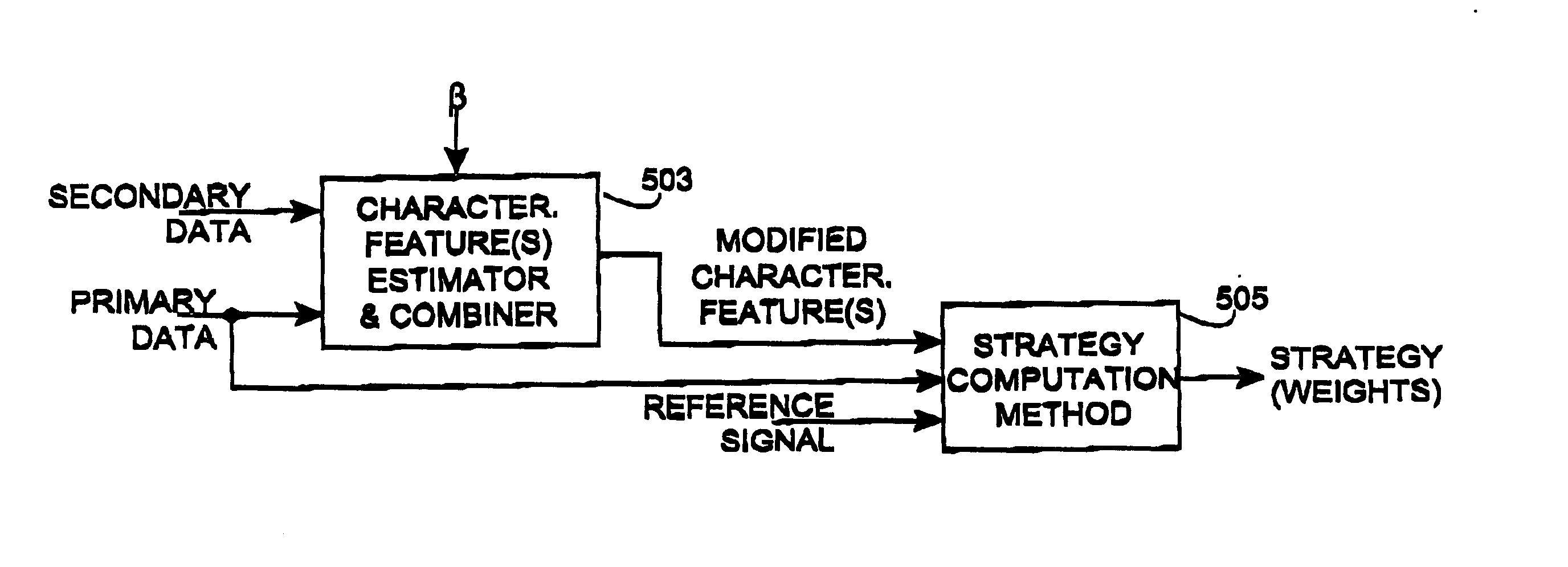
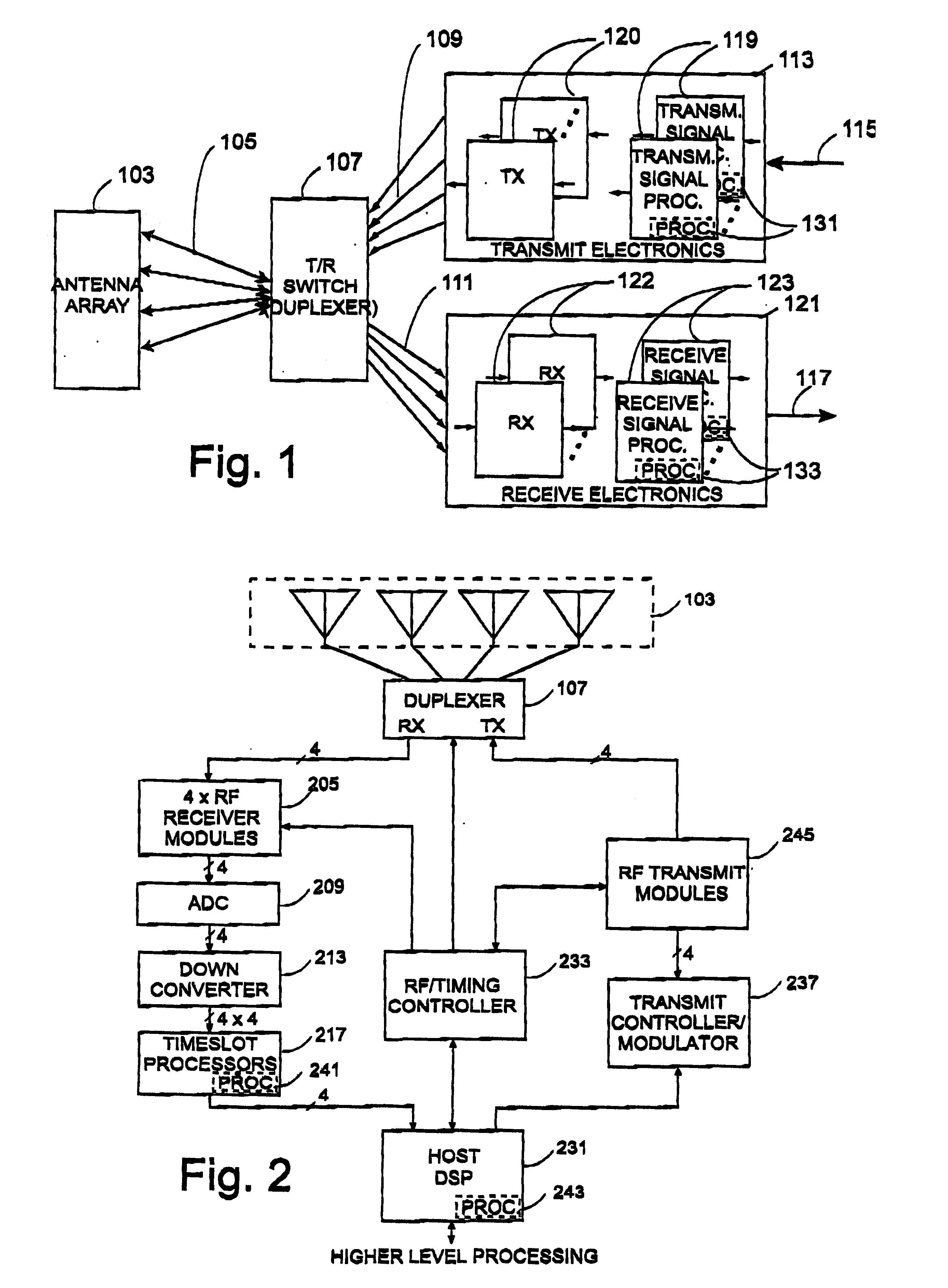
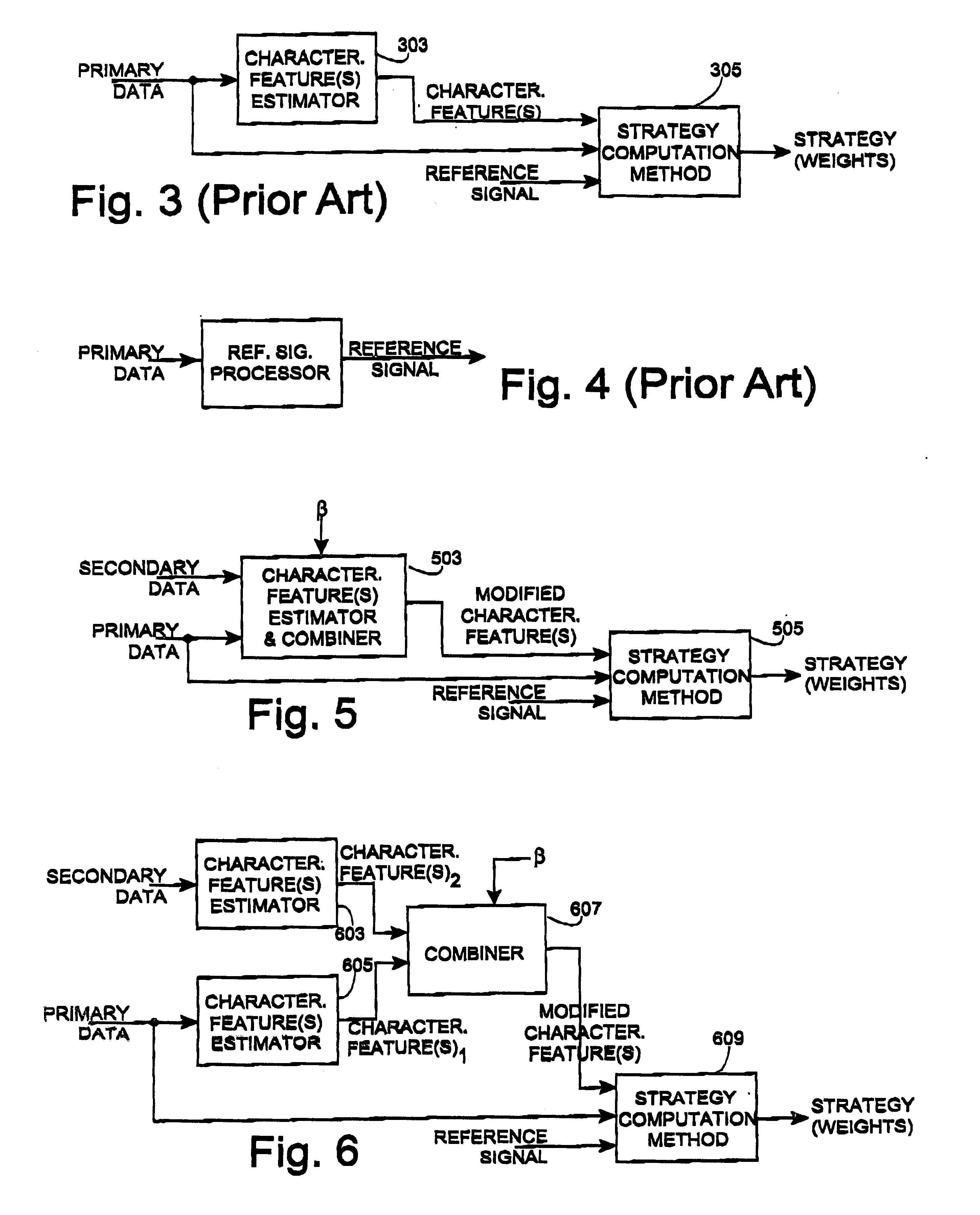
The invention is directed to a processing method for altering the transmit or receive weights used by a communication station to define a transmitted signal or to process a received signal in order to take into account the presence of a changing interference environment, and apparatus for implementing the same. The invention may be implemented in a communication station that includes a receiver, an array of antennas and means for adaptive smart antenna processing of received signals. The invention may also be implemented in a communication station that includes a transmitter, an array of antennas, and means for adaptive smart antenna processing of transmitted signals. In a preferred embodiment, the communication station includes a transceiver and the capability of implementing both uplink and downlink adaptive smart antenna processing.

When receiving a signal from a subscriber (remote) unit, the signals received by each of the antenna array elements a...


PUM


Abstract

An apparatus and method for adaptively producing transmitted signals and processing received signals in a communication system which includes smart antenna array of antenna elements. When processing received signals, the invention modifies an existing processing scheme by incorporating information about a second set of signals for which training or other characteristic information such as a reference is unknown to information about a first set of signals for which characteristic information such as a reference is known, prior to executing the processing scheme. This approach can be used to modify the receive weights which determine the relative weight assigned to the signals received from each of a plurality of antenna elements to take into account the presence of a changing interference environment. This permits an adaptive updating of the receive weights based on the additional information provided by the second set of data, and may be accomplished faster and with less computational resources than required to determine the weights based on applying the entire processing scheme to the second set of data. In addition, assuming a relationship between the transmit and receive environment, the invention can also be used to modify the transmit weights used by the base station.

Description

FIELD OF THE INVENTIONThe present invention relates to the field of wireless communication systems, and more specifically, to an apparatus and method for improving the formation of transmitted signals and processing of received signals by altering the beam shaping characteristics of the antenna elements in a receiving or transmitting communication station that includes an array of antenna elements to take into account a changing interference environment.BACKGROUNDAdaptive smart antenna processing may be used in a communication station (e.g., a base station) equipped with multiple antennas to either reject interference when communicating from a subscriber unit to the communication station (i.e., on the uplink) or to deliver power in a spatially or spatio-temporally selective manner when communicating from the communication station to a subscriber unit (i.e., on the downlink). Smart antenna communication systems may use linear spatial processing as part of the adaptive smart antenna p...

Claims


Application Information

Patent Timeline
IPC IPC(8): H04B7/04H04B7/06H04B7/08H01Q3/26H04B7/10H04B7/26H04L1/06
CPCH04B7/0615H04B7/0619H04B7/0848H04B7/0851H04L25/0204H04L25/021H04B7/0617H04L25/03299H04L25/03203H04L25/0328H04B7/086
Inventor YOUSSEFMIR, MICHAELTROTT, MITCHELL D.KARUPPIAH, KAMARAIPETRUS, PAUL
Owner INTEL CORP
Why Eureka
Try Eureka