However, in many wall constructions, the top end of the studs are not rigidly secured to the upper channel.
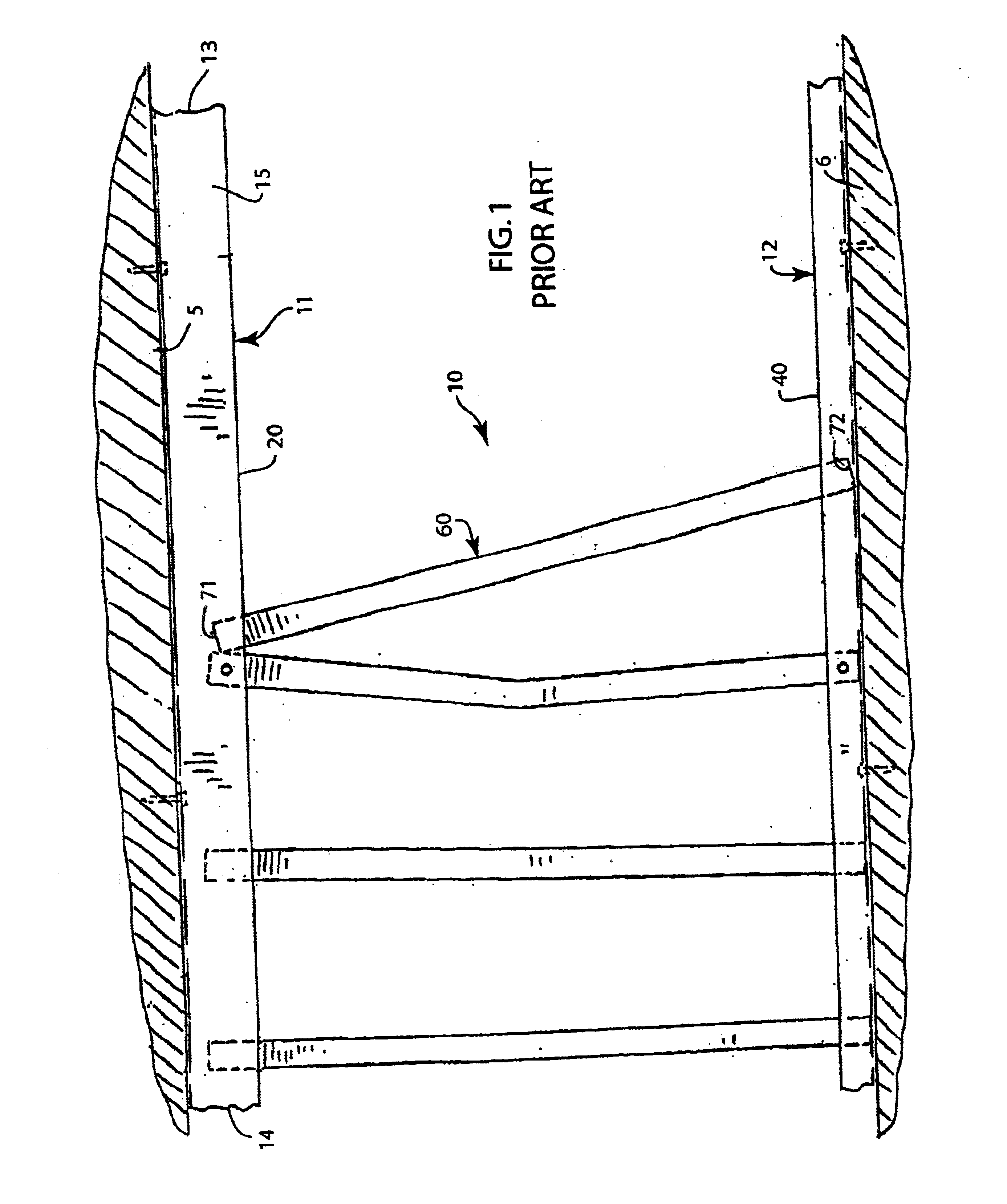
As shown in FIG. 1, the construction personnel performing this work can inadvertently bump or intentionally move the studs from their intended positions.
If the studs are screwed or riveted in place, they are difficult to move and may be bent by the workers.
Once this insulation is installed, it is difficult to reposition the support studs if they are out of their desired vertical, evenly spaced positions.
The electrical, plumbing and duct work will invariably result in the necessary repositioning of some studs.
Still, many studs are left out of their desired position because the workers cannot easily realign them.
The end result is that the studs are often left out of place and are difficult to locate once the
drywall or paneling is installed.
A problem with temporarily riveting or screwing the studs to the upper channel to maintain the desired stud alignment is that these fasteners need to be removed before the
drywall or paneling is mounted to the wall frame.
The wall frame is then improperly fixed to the ceiling, which can crush or buckle the studs,
drywall, paneling or other wall components.
A problem with using slots to align and hold the studs in a wall frame is that hundreds of slots must be individually formed by hand at the construction site.
Accordingly, these slots are labor intensive and costly to form.
Another problem with conventional slot forming methods is that the slots are inconsistently sized and shaped.
The result is a lack of uniformity in fold geometry and slot width.
Yet, a narrow slot will not receive a stud, or it will hold the stud too tightly so that it cannot be easily inserted or removed.
Narrow slots can also cause the studs to bind against the upper channel during use, which can damage the stud and wall.
A slot that is too wide will not properly retain the stud, so that the stud can fall out or be easily bumped out of its slot.
A further problem is that the slits are not made to a consistent length or depth.
Slits that are too long will unnecessarily weaken the channel.
Slits that are too short will create folds that are not strong enough to retain the stud.
A still further problem with forming the slots is that at least two different hand tools are needed to create each slot.
A still further problem in forming slots into the channel is that conventional bending tools, such as a pair of pliers, do not enable a worker to easily bend and tear the folds to a consistent shape or geometry.
A conventional pair of pliers also has no guide to enable the worker to correctly tear the channel to form a rectangular fold having a specific width, or bend the fold to a consistent angle relative to the vertical side of the channel.
A still further problem in forming the slots is that they are not efficiently formed by conventional cutting and bending tools.
These steps must be repeated several hundred times. Each step takes time, and adds to the cost of the wall.
A still further problem with many conventional cutting tools is that they are difficult to use to
cut the
metal channel.
A worker can become fatigued making the hundreds of cuts needed to form the channels throughout the building, particularly for thicker gauge channels, and can lead to inconsistencies in the formation of the slots.
Yet, a tool with long handles can be unwieldy, especially when the slots are being formed in an upper channel several feet above the worker.
The worker can easily crush the channel when aligning or stroking the tool, particularly for thinner gauge channels.
A still further problem with many conventional cutting tools is that their blades will quickly dull when cutting thicker gauge channels.
The cutting blades cannot be easily removed and replaced with sharp blades.
Thus, the costs associated with using these types of cutting tools is needlessly inflated.

