Assembly for crimping an intraluminal device or measuring the radial strength of the intraluminal device and method of use

a technology for intraluminal devices and stents, which is applied in the direction of prosthesis, manufacturing tools, blood vessels, etc., can solve the problems of non-uniform stent crimping, blood clots in the vasculature, and sharp edges along the now uneven surface of the crimped stent, so as to achieve accurate measurement of the radial strength of the stent and reduce the diameter, the effect of convenient us

Inactive Publication Date: 2005-01-11
ABBOTT CARDIOVASCULAR
View PDF154 Cites 56 Cited by
  • Summary
  • Abstract
  • Description
  • Claims
  • Application Information

AI Technical Summary

Benefits of technology

The present invention provides for a stent crimping or compressing assembly that is easy to use, and provides a tight and reliable crimped stent onto the distal portion of a stent delivery catheter. Preferably, the stent crimping assembly is used to crimp an expandable stent onto the balloon portion of a catheter, however, the device can be used with self-expanding stents as well. The terms crimping and compressing as used herein are meant to be interchangeable and mean that the diameter of the stent is reduced to some degree. Typically, balloon-expandable stents are known by persons having ordinary skill in the art to be “crimped” onto the balloon portion of a catheter while self-expanding stents are compressed onto a mandrel

Problems solved by technology

Non-uniform crimping can result in sharp edges being formed along the now uneven surface of the crimped stent.
Furthermore, nonuniform stent crimping may not achieve the desired minimal profile for the stent and catheter assembly.
Where the stent is not reliably crimped onto the catheter, the stent may slide off the catheter and into the patient's vasculature prematurely as a loose foreign body, possibly causing blood clots in the vasculature, including thrombosis.
This crimping is sometimes done by hand, which can be unsatisfactory due to the uneven application of force resulting in non-uniform crimps.
In addition,

Method used


Image

  • Assembly for crimping an intraluminal device or measuring the radial strength of the intraluminal device and method of use
  • Assembly for crimping an intraluminal device or measuring the radial strength of the intraluminal device and method of use
  • Assembly for crimping an intraluminal device or measuring the radial strength of the intraluminal device and method of use

Examples


Embodiment Construction

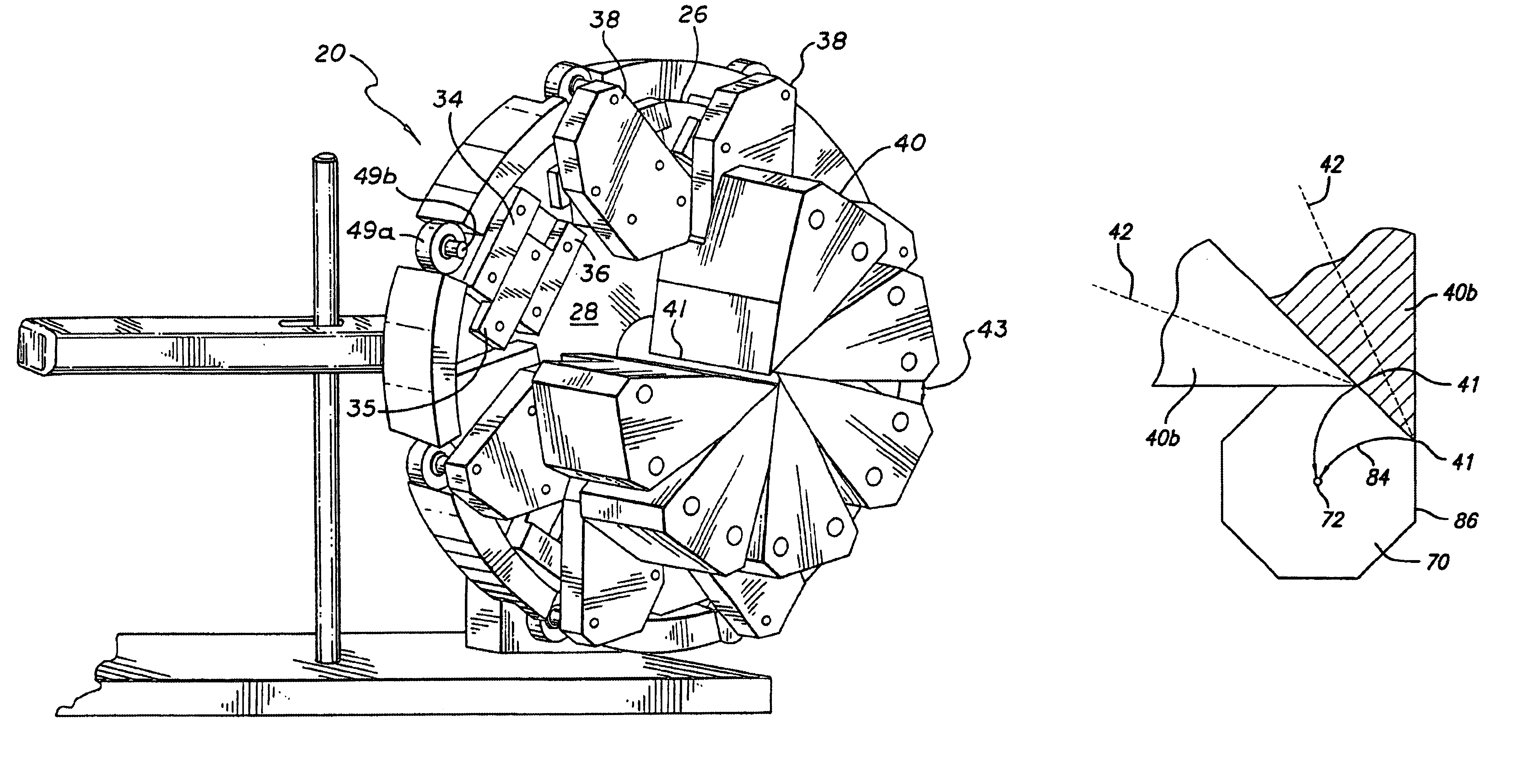
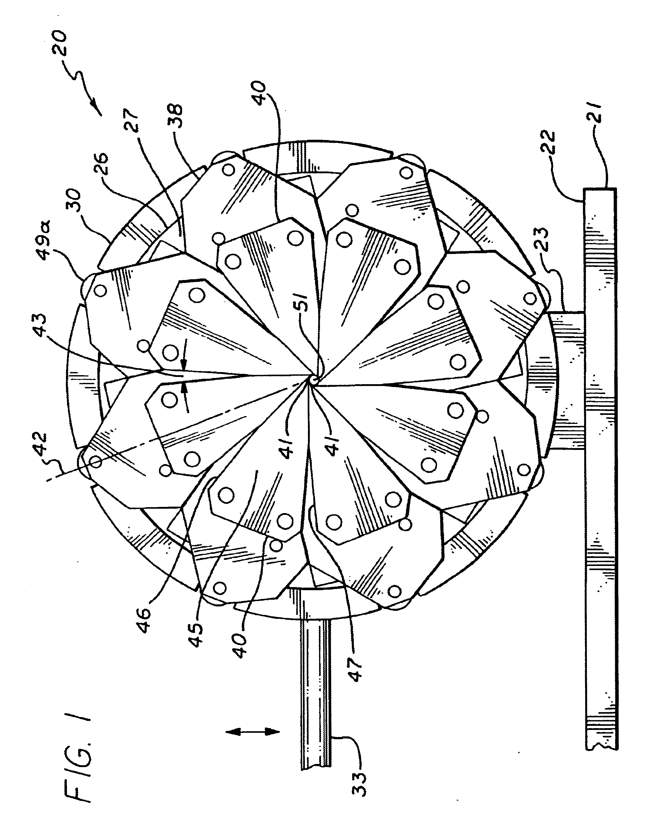
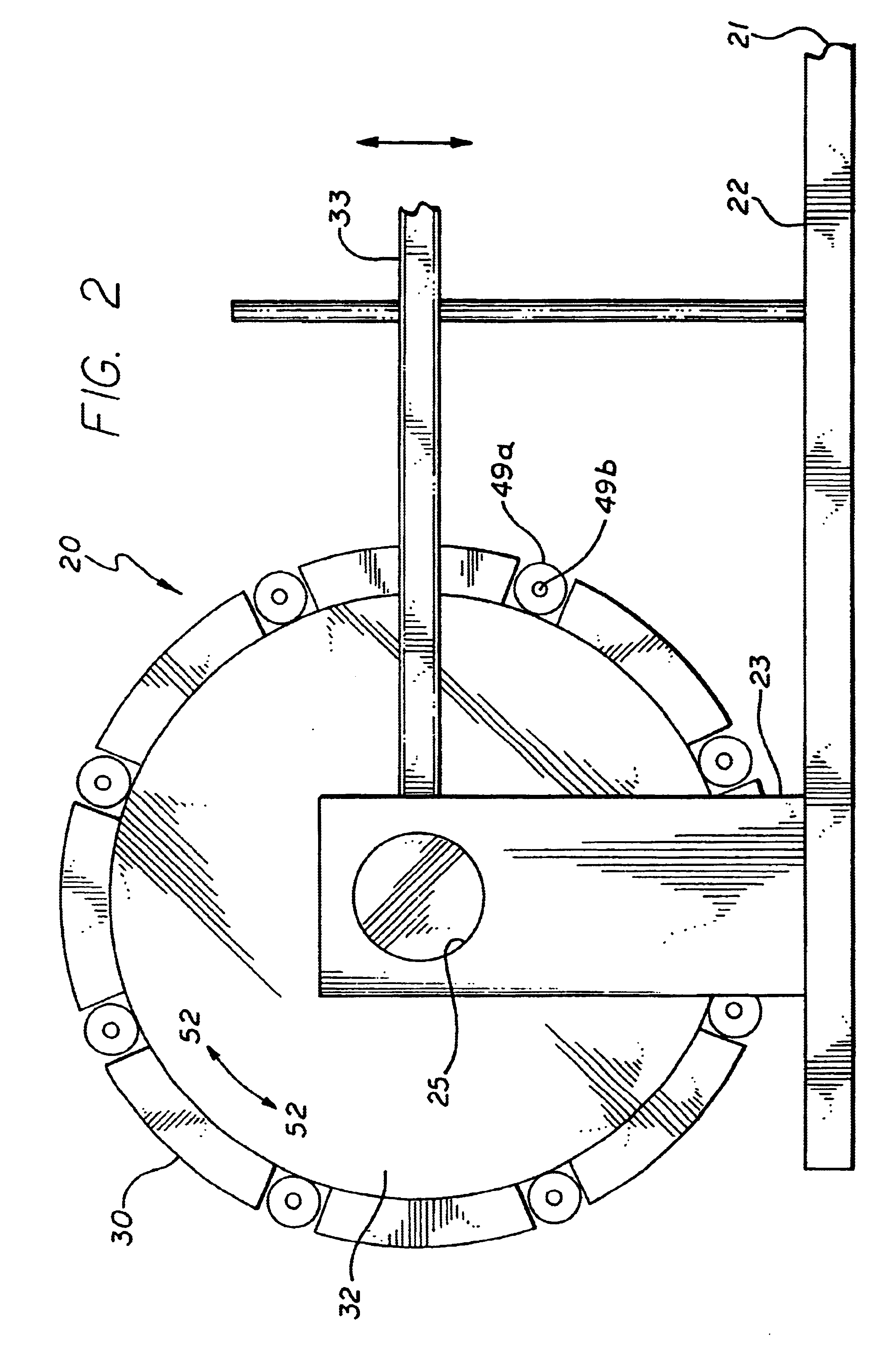
The present invention stent crimping assembly provides for a reliable and uniform crimp of any stent onto a catheter. The stent crimping assembly is capable of crimping almost any size stent, or length of stent, onto the distal portion of a catheter, including stents for coronary arteries and peripheral arteries. The terms crimping and compressing as used herein are meant to be interchangeable and mean that the diameter of the stent is reduced to some degree. Typically, balloon-expandable stents are known by persons having ordinary skill in the art to be “crimped” onto the balloon portion of a catheter while self-expanding stents are compressed onto a mandrel or sheath and then inserted into a catheter. Also, references to “stent crimping assembly” as used herein is not meant to be limiting since the assembly can be used as a measuring device to accurately measure the radial strength of a stent. Thus, for ease of reference, the device has been referred to throughout as a stent crimp...


PUM

PropertyMeasurementUnit
Angleaaaaaaaaaa
Angleaaaaaaaaaa
Angleaaaaaaaaaa

Abstract

An assembly is provided which can crimp or compress an intraluminal device or measure the radial strength of an intraluminal device. The device includes a first disk and a second disk for imparting movement to a number of spaced apart moving elements attached to linear sliders on the first disk. In one configuration, rotational movement is imparted to the second disk which causes the tips of the moving elements to move is a linear direction toward the center of the opening formed by the elements thereby closing in on the device. In another configuration, rotational movement is imparted to the first disk and the tips move along an arcuate path from the perimeter of the opening toward the center of the opening.

Description

BACKGROUND OF THE INVENTIONThe present invention relates to an apparatus for loading an intraluminal device, such as a stent or an embolic device such as a filter, onto the distal end of a catheter assembly similar to those used, for example, in percutaneous transluminal coronary angioplasty (PTCA) procedures or in percutaneous transluminal angioplasty (PTA) procedures. The present invention device is useful in crimping balloon-expandable stents and self-expanding stents.In typical PTCA procedures, a guiding catheter is percutaneously introduced into the cardiovascular system of a patient through the brachial or femoral arteries and advanced through the vasculature until the distal end of the guiding catheter is in the ostium of the aorta leading to the coronary arteries. A guide wire and a dilatation catheter having a balloon on the distal end are introduced through the guiding catheter with the guide wire sliding within the dilatation catheter. The guide wire is first advanced out...

Claims


Application Information

Patent Timeline
IPC IPC(8): A61F2/06A61F2/84
CPCA61F2/958Y10T29/53996A61F2002/9522A61F2/9522A61F2/9526
Inventor KOKISH, ARKADY
Owner ABBOTT CARDIOVASCULAR
Why Eureka
Try Eureka