
Footing form

a footing and form technology, applied in the field of concrete forms, can solve the problems of impracticality, high material cost, and certain structural limits of tapered prefabricated forms, and achieve the effect of preventing the hazard of open trenches and small heigh

Inactive Publication Date: 2005-01-11
BIGFOOT SYST
View PDF5 Cites 10 Cited by
  • Summary
  • Abstract
  • Description
  • Claims
  • Application Information

AI Technical Summary

Benefits of technology

It is another object of the present invention to provide a prefabricated form for molding a pillar footing of a concrete structural material, which form is shaped to ensure complete filling with the concrete material without entrapped air pockets, while preventing excessive height of the form at large footprints.
It is still another object of the invention to provide a prefabricated form for molding a pillar footing of a concrete structural material, which form is shaped to prevent cave-in of the form upon backfilling prior to filling of the form with the concrete material.
These objects are now achieved in a prefabricated footing form in accordance with the invention by controlling the dimensions of the form of substantially tapered shape according to strict structural relationships in order to reduce the amount of material needed for manufacture of the form, to ensure proper filling of the form with concrete material, to maintain the height of the form within practical limits, and to prevent cave-in upon backfilling of the form prior to pouring of the concrete material.
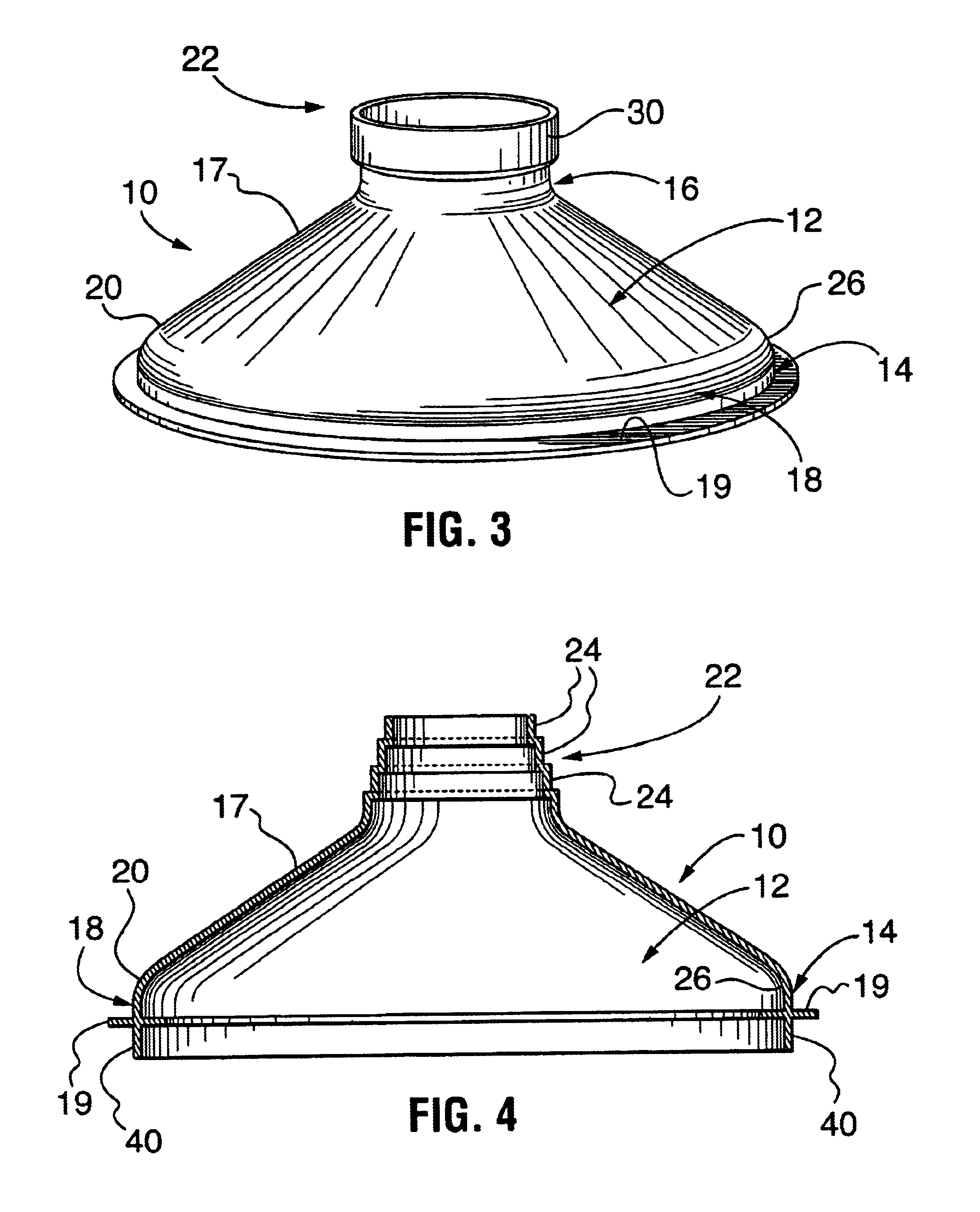
In accordance with the invention, a preferred footing form for molding a footing of concrete material at a bottom end of a concrete column, includesa substantially tapered rigid hollow body having a circular top end of a first diameter DT, a bottom end of a larger, second diameter DB, the bottom end defining a base plane and being concentrically, vertically spaced from the top end by a height H, and an integral side wall extending between the top and bottom ends, at least a portion of the sidewall being inclined at a sidewall angle below 45° with respect to the base plane, the sidewall having a length S parallel in axial direction of the footing form;a circular top flange at the top end for fittingly supporting a prefabricated tubular column form, and a bottom flange at the bottom end for supporting the footing form on a suitably prepared substrate;whereby the dimensions of DT, DB, H and S are selected such that S≦2.4 h for reducing the amount of material used to manufacture the footing form, S≧0.55ΔD, with ΔD=DB−DT for preventing cave-in of the form upon exterior backfilling prior to molding of the footing, DB≧1.8DT for lateral stability of the footing form, ½ΔD≧H≧¼ΔD for DB≧24 inches for preventing excessive footing form heights, and DT≧½DB−H for ensuring proper filling of the footing form with a concrete mixture of about 3000 psi to 4000 psi.
It is a principal advantage of the prefabricated footing form in accordance with the invention that it has a relatively small height even for large footprints, while still permitting backfilling before the concrete is poured, preventing the hazard of open trenches.

Problems solved by technology

However, tapered prefabricated forms have certain structural limits.
Such a sidewall angle is impractical for industrial size applications with large footprint (bottom diameter), for example above 30 inch diameter, since it will lead to an impractically high form and high material cost.
Thus, since the vertical location of this transition region is governed by the height of the footing form, forms of large footprint and a sidewall angle of 45° or above are impractical and uneconomical due to high installation and / or excavation cost.

Method used


Image

  • Footing form
  • Footing form
  • Footing form

Examples


Embodiment Construction

Despite the structural limitations taught in the prior art, it has now been surprisingly found that a form having a sidewall angle below 45° will reliably fill with a concrete mixture of at most about 3000 psi, as long as other structural limitations of the form follow certain strict relationships. Through extensive research, the applicant has developed certain structural relationships which, if strictly followed, allow the manufacture of prefabricated forms that will still reliably fill with a concrete mixture of up to 4500 psi, despite a sidewall angle below 45° and even as low as about 30°, and without vibration of the concrete. However, if these structural limitations as developed in accordance with the invention are not followed, the form may not fill properly, or even more disastrous results may occur, such as cave-in of the form.

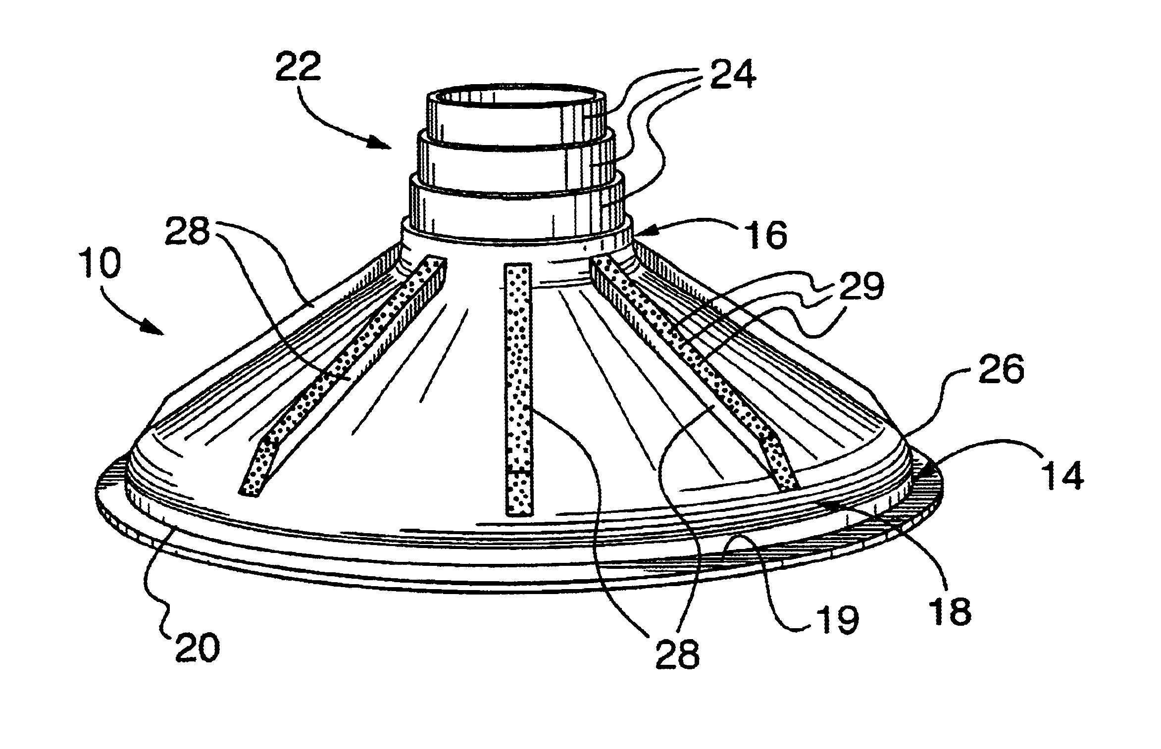
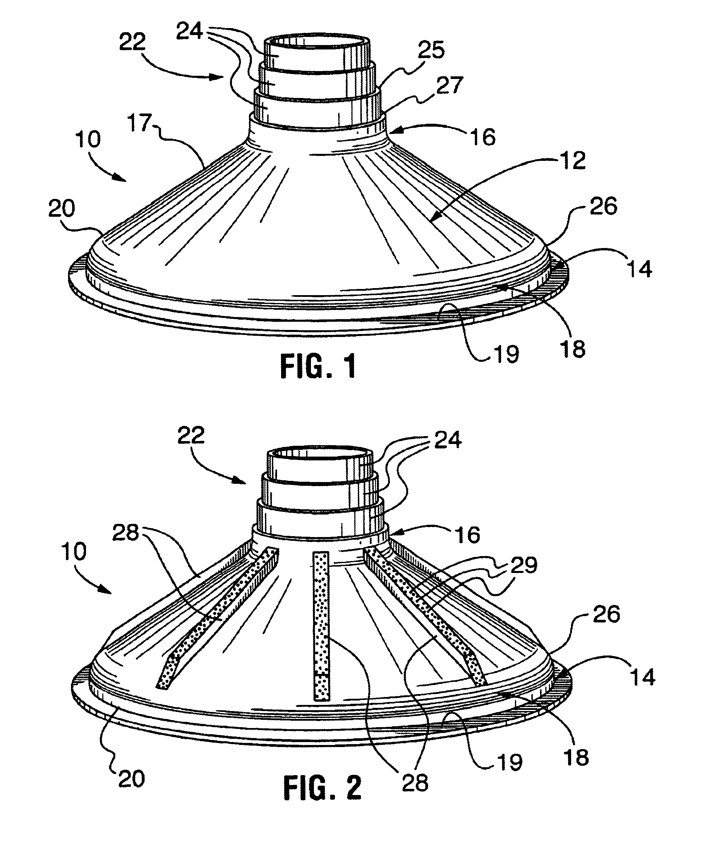
FIG. 1 shows a perspective view of a first embodiment of a prefabricated footing form 10 in accordance with the invention. The prefabricated form 10 ...


PUM


Abstract

A prefabricated concrete form for the pouring of a footing for a structural pillar is disclosed. The form is preferably constructed from a thermoplastic such as a high density polyethylene or ABS and is molded as a single disposable unit. The form is bell-shaped and has dimensions which render it useful in industrial size applications with large footprints. The dimensioning of the form also reduces the amount of material used for the manufacture of the form, allows the form to be backfilled without cave-in and to reliably support a tubular form for the pillar without an additional bracing or supporting structure. The form is in particular a low profile form wherein the sidewall is inclined at an angle below 45° relative to the bottom edge. A top flange of the form is preferably adapted to accommodate two or more different diameters of the tubular form for the structural pillar. The sidewall may include integral ribs which open inwardly to facilitate evacuation of air as the form is filled and to lend rigidity to the sidewall. The sidewall may further include vent openings for the escape of air which is possibly temporarily entrapped during filling of the form. The advantage is an inexpensive form which does not have an excessive height despite large footprints, fills reliably and supports a tubular form for a pillar without the need for cross-pieces, even at sidewall angles below 45°.

Description

FIELD OF THE INVENTIONThis invention relates to concrete forms for materials such as concrete, polymer concrete or the like and, in particular, to forms for molding footings for structural pillars used in the construction industry.BACKGROUND OF THE INVENTIONThe use of structural pillars made from a concrete material is well known and widely practiced in the construction industry. Such pillars are typically poured into a tubular pillar form made of spirally wrapped paper, although other prefabricated pillar forms are well known and commonly used for this purpose. According to most building codes, structural pillars must be supported by a footing located below the level of maximum frost penetration and usually set on a coarse aggregate bed to ensure adequate drainage. The footing which is normally also made of concrete material provides support for the pillar and its load. Traditionally, wooden footing forms built on site were used. More recently, prefabricated forms have been introdu...

Claims


Application Information

Patent Timeline
Patent Type & Authority Patents(United States)
IPC IPC(8): E02D27/32E02D27/42E02D5/34E02D5/44
CPCE02D27/42E02D5/44
Inventor SWINIMER, KIRK
Owner BIGFOOT SYST
Learn More