Method and apparatus for vertical board construction of fiber optic transmitters, receivers and transceivers

a technology of fiber optic transmitters and receivers, applied in the field of light bending devices, can solve the problems of increasing the cost of fiber optic transceivers, requiring additional components for using separate optical elements, and emi, so as to reduce the footprint of fiber optic modules, avoid optical crosstalk, and minimize manufacturing costs

Inactive Publication Date: 2005-01-11
JDS UNIPHASE CORP
View PDF442 Cites 28 Cited by
  • Summary
  • Abstract
  • Description
  • Claims
  • Application Information

AI Technical Summary

Benefits of technology

Briefly, the present invention includes a method, apparatus and system for method and apparatus for vertical board construction of fiber optic transmitters, receivers and transceivers as described in the claims. Fiber optic transmitter and receiver electrical elements are implemented on two separate substantially parallel boards in a fiber optic module. The parallel boards are mount substantially perpendicular to the base of the fiber optic module and the system printed circuit board to which it attaches, to reduce the footprint of the fiber optic module. In one embodiment, bending light or photons through ninety degrees, the light transmitter (a packaged type of emitter) and a light receiver (a packaged type of photodetector) are each mounted substantially perpendicular to the transmit and receive boards respectively such that their active areas are nearly facing each other but offset. A single optical block implements lenses and reflecting surfaces to minimize manufacturing costs. The light receiver and light transmitter are mounted offset from each other in the optical block in order to avoid optical cross talk. In a second embodiment, the light transmitter (emitter) and the light receiver (photodetector) are each mounted substantially parallel with the transmit and receive boards respectively and the connection to the optical fibers. The separate and substantially parallel receive and transmit boards are provided with ground planes on back sides in order to minimize electrical cross talk. A module outer shielded housing, manufactured out of metal or metal plated plastic, provides further shielding for EMI. The substantially parallel boards may be extended to support multiple channels or multiple parallel fibers such as in a ribbon optical fiber cable. Manufacturing steps of the boards for the fiber optic module are disclosed to provide reduced manufacturing costs.

Problems solved by technology

Additionally, electromagnetic interference (EMI) is of concern due to the high frequency of operation of the fiber optic modules.
Using separate optical elements requires additional components and increases the costs of fiber optic transceivers.
Previously, the fiber optic transceiver, receiver, and transmitter utilized horizontal boards or substrates which mounted parallel with a system printed circuit board utilized significant footprint or board space.
However, the horizontal boards, parallel to the system printed circuit board, required large spacing between optical fiber connectors to make the connection to the optical fibers.
Additionally, the desire for tighter interconnect leads of fiber optic cables, restricts the size of the OE's.
This severely restricts the method of coupling light or photons from the OE into and out of fiber optic cables.

Method used


Image

  • Method and apparatus for vertical board construction of fiber optic transmitters, receivers and transceivers
  • Method and apparatus for vertical board construction of fiber optic transmitters, receivers and transceivers
  • Method and apparatus for vertical board construction of fiber optic transmitters, receivers and transceivers

Examples


second embodiment

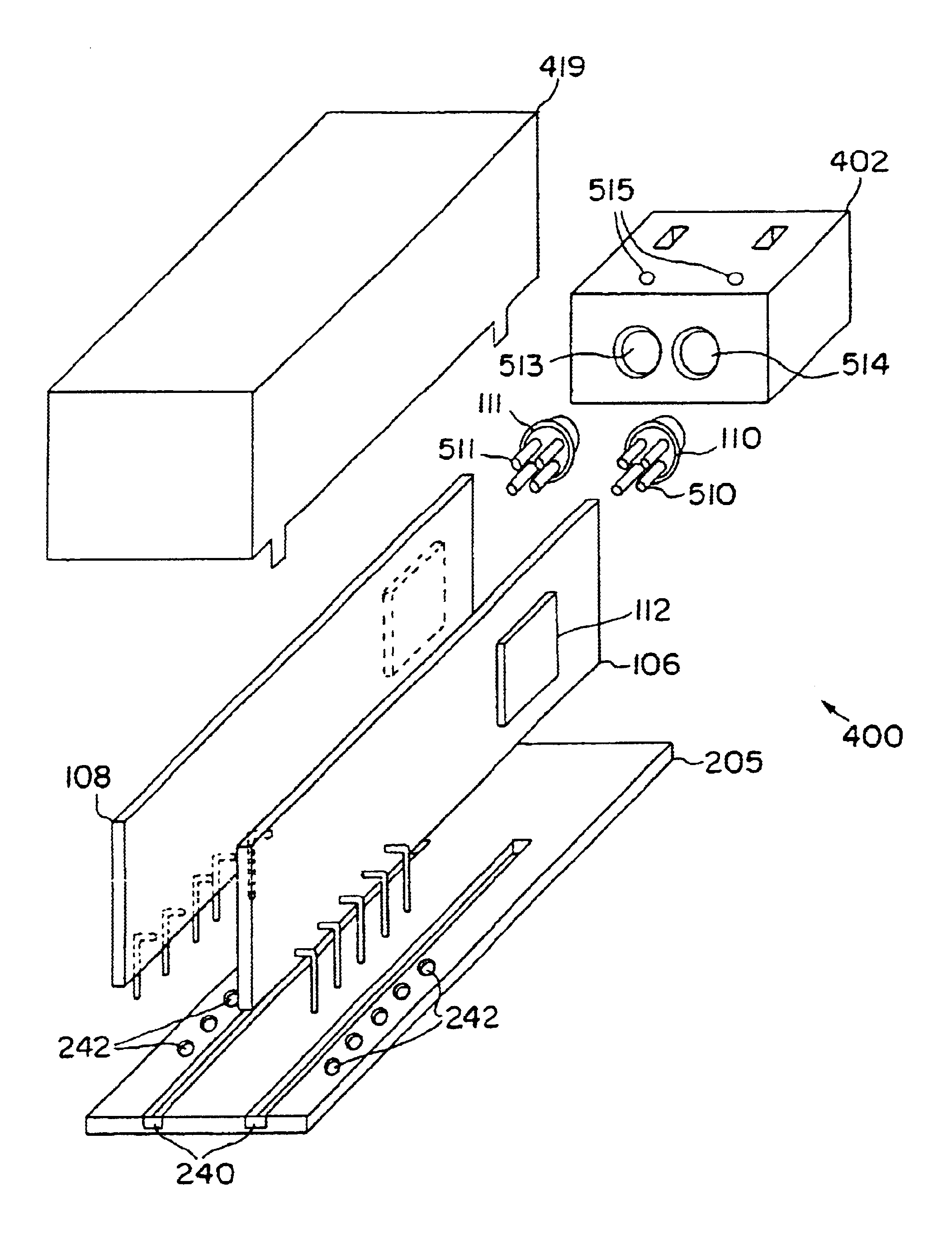
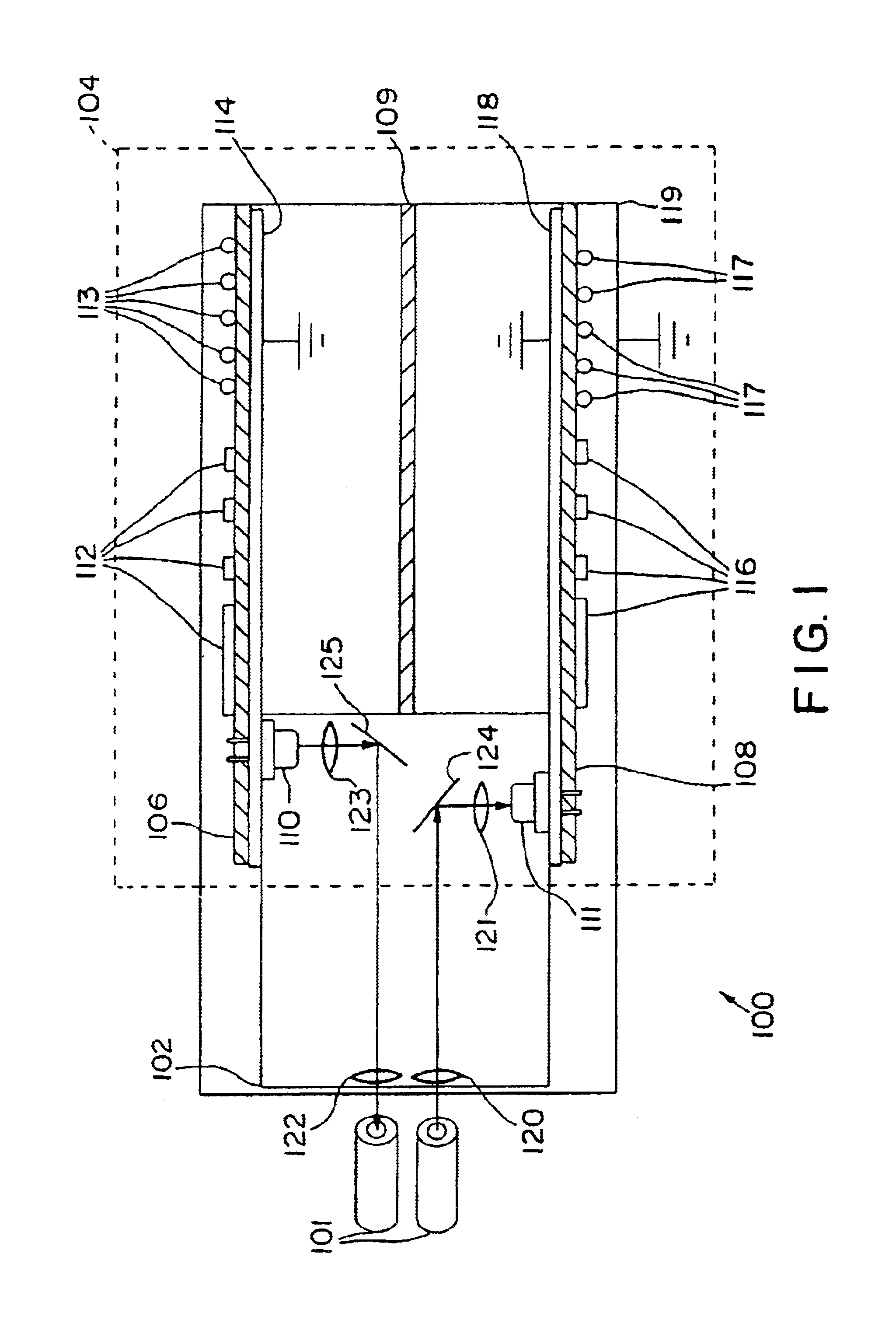
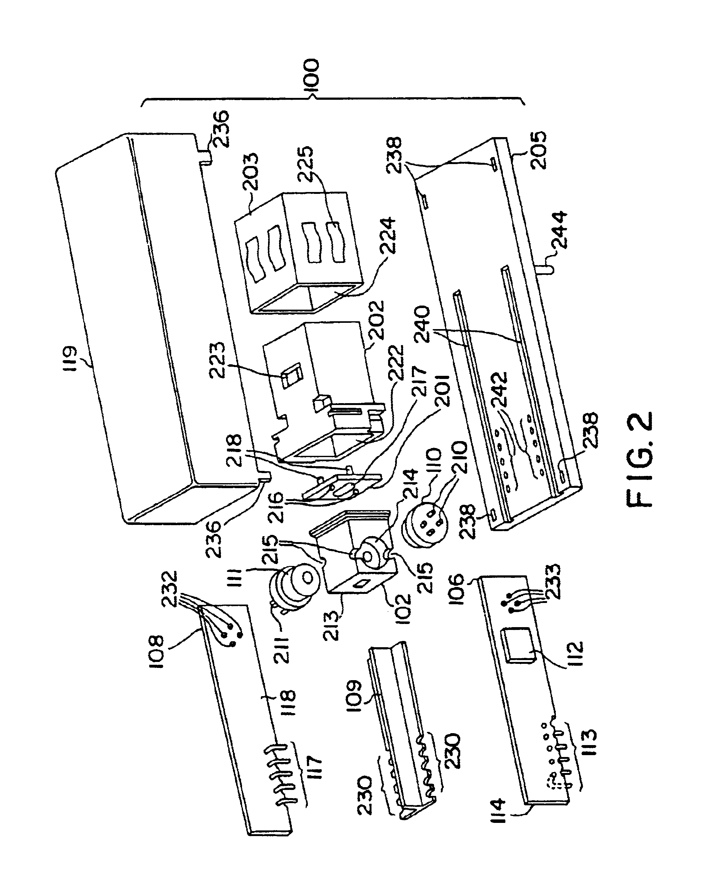
The present invention includes a method, apparatus and system for method, apparatus and system for vertical board construction of fiber optic transmitters, receivers and transceivers. Briefly, fiber optic transmitter and receiver electrical elements are implemented on two separate substantially parallel boards in a fiber optic module. The parallel boards are mount substantially perpendicular to the base of the fiber optic module and the system printed circuit board to which it attaches, to reduce the footprint of the fiber optic module. In one embodiment, bending light or photons through ninety degrees, the light transmitter (a packaged type of emitter) and a light receiver (a packaged type of photodetector) are each mounted substantially perpendicular to the transmit and receive boards respectively such that their active areas are nearly facing each other but offset. A single optical block implements lenses and reflecting surfaces to minimize manufacturing costs. The light receiver...


PUM


Abstract

Fiber optic transmitter and receiver electrical elements are implemented on separate vertical boards in fiber optic modules. A single optical block implements lenses and reflecting surfaces to minimize manufacturing costs. In one embodiment the receiver and transmitter are mounted to receive and transmit vertical boards respectively to nearly face each other but being offset to avoid optical cross talk. In a second embodiment, receiver and transmitter are mounted parallel with the printed circuit boards to save additional space. The vertical boards have ground planes to minimize electrical cross talk. A shielded housing provides further shielding for EMI. Manufacturing steps of the fiber optic transceiver are disclosed which provide reduced manufacturing costs.

Description

FIELD OF THE INVENTIONThis invention relates generally to light bending devices. More particularly, the invention relates to fiber optic modules.BACKGROUND OF THE INVENTIONFiber optic modules interface optical fibers to electronic circuitry transducing communication by light or photons with communication by electrical signals. A fiber optic module may be a fiber optic receiver, transmitter or transceiver including both receive and transmit functions. The fiber optic receiver, transmitter and transceiver each have optical elements (OE) and electrical elements (EE). The fiber optic transmitter OE includes an emitter (such as a semiconductor LED or Laser) mounted in a package and an optical coupling element for coupling light or photons from the OE into the optical fiber. The type of semiconductor laser (light amplification by stimulated emission of radiation) may be a vertical cavity surface emitting laser (VCSEL). The fiber optic receiver OE includes a photodetector (such as a photod...

Claims


Application Information

Patent Timeline
Patent Type & Authority Patents(United States)
IPC IPC(8): G02B6/42H01S5/022H01S5/183H04B10/2507H04B10/40H04B10/43H04B10/50H04B10/60
CPCG02B6/4204G02B6/4214G02B6/4292G02B6/4246G02B6/4277G02B6/422
Inventor JIANG, WENBINWEI, CHENG PING
Owner JDS UNIPHASE CORP
Why Eureka
Try Eureka