Plasma source with reliable ignition

a reliable, plasma source technology, applied in the direction of ion implantation coating, chemical vapor deposition coating, coating, etc., can solve the problems of high-voltage plasma ignition, low efficiency, and inability to achieve desired effects, and achieve the effect of reducing the arcing ra

Inactive Publication Date: 2005-01-11
LEYBOLD OPTICS
View PDF16 Cites 8 Cited by
  • Summary
  • Abstract
  • Description
  • Claims
  • Application Information

AI Technical Summary

Benefits of technology

[0016]The advantage attained with the invention comprises in particular that even without a pressure increase or at only minimal pressure increase in the plasma volume, the plasma can be ignited by merely applying the high-frequency voltage. In addition, the tendency to arcing is considerably reduced.

Problems solved by technology

Of disadvantage in this plasma source is that it ignites only with a pressure pulse, i.e. to ignite the source, the pressure in the plasma volume of p=0.02 Pa must be raised to p>1 Pa.
In contrast for example to a fluorescent tube, which operates at higher pressures, the use of a high voltage for the plasma ignition is practically not possible, or at least highly elaborate, due to the extremely high ignition voltage.
Therewith the ions collide frequently with gas molecules and, on the way to the substrate to be treated, lose so much energy that the desired effect fails to appear, i.e. there are virtually no incoming ions.
However, this auxiliary recess does not serve for ignition.
These ignition aids, however, are highly maintenance- and / or cost-intensive.

Method used


Image

  • Plasma source with reliable ignition
  • Plasma source with reliable ignition

Examples


Embodiment Construction

high-frequency voltage. In addition, the tendency to arcing is considerably reduced.

[0017]An embodiment example of the invention is depicted in the drawing and will be described in further detail.

BRIEF DESCRIPTION OF THE DRAWINGS

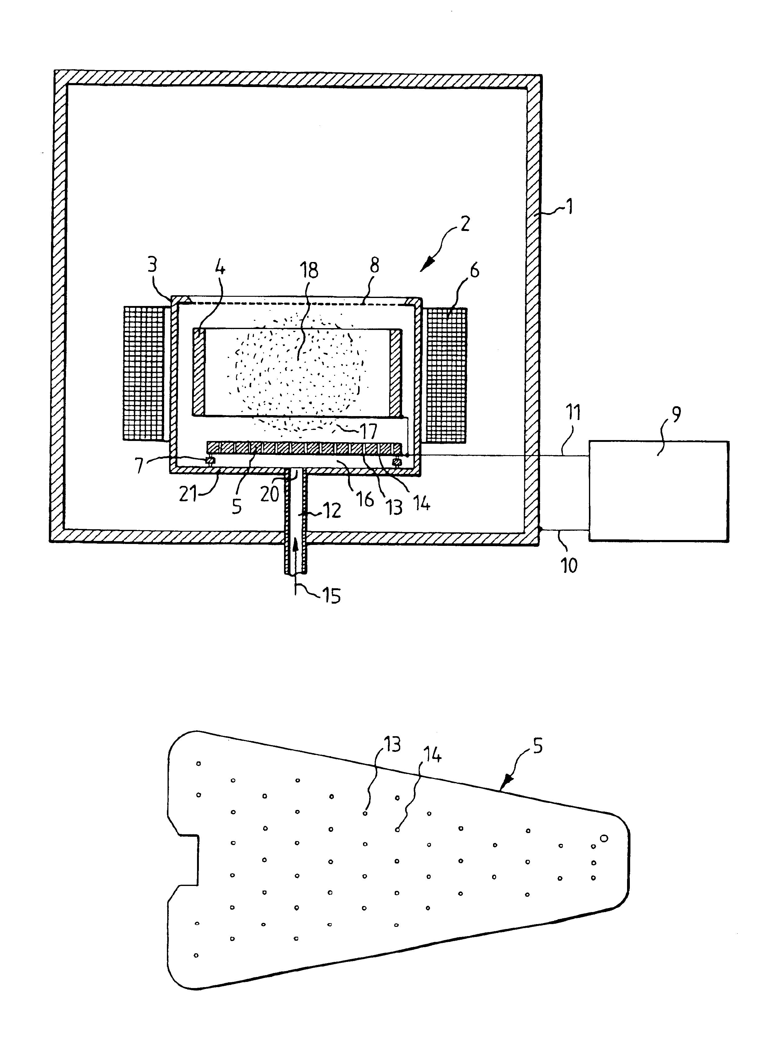
[0018]FIG. 1 a plasma source, located in a vacuum chamber,

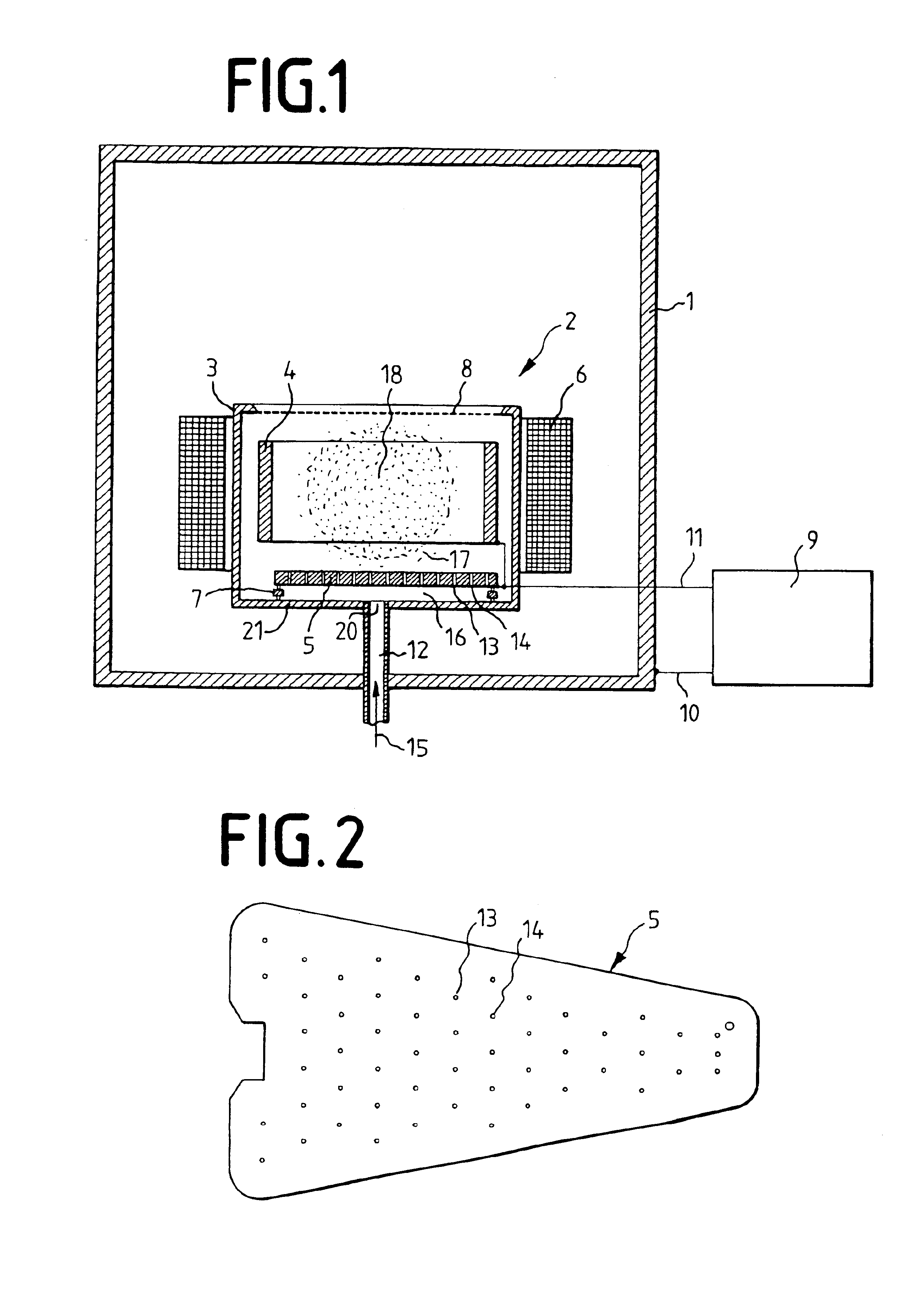
[0019]FIG. 2 a plate, which can be utilized in the plasma source.

DETAILED DESCRIPTION

[0020]FIG. 1 shows a vacuum housing 1, in which substrates can be coated or etched. These substrates are not shown in the schematic representation. They would be located opposite a plasma source 2, which is disposed within the vacuum housing 1. The plasma source 2 comprises, in turn, a chamber 3, which encompasses an induction loop 4 as well as a cathode plate 5. The induction loop can be comprised of a coil with one or several windings. If it consists of only one winding, it is developed as a circular curved metal sheet which encompasses the plasma. About the chamber 3 is placed a coil 6, with which a magnetic field ...


PUM

PropertyMeasurementUnit
diameteraaaaaaaaaa
pressureaaaaaaaaaa
lengthaaaaaaaaaa

Abstract

The invention relates to a plasma source whose plasma is ignited by an electric voltage. To be able to carry out the ignition at relatively low voltages, a plate (5) provided with holes (13, 14) is provided beneath a plasma volume (17), which is disposed above a wall (21) of a plasma chamber (3). Through this plate (5) an ignition volume (16) is formed beneath the plasma volume (17) with a higher pressure than in the plasma volume (17), in which the plasma ignites first. The ignition is subsequently propagated through the holes of the plate (5) into the plasma volume (17).

Description

FIELD OF THE INVENTION[0002]The invention relates to a plasma source having a chamber, a plate at a spacing from a wall of the chamber in which plasma is generated, with this plate comprising throughbores, through which gas can flow into a plasma volume, whereby this plate forms with the wall of the chamber a closed volume and a gas inlet.[0003]A plasma, in general, is comprised of a mixture of three components: free electrons, positive ions and neutral atoms or molecules. The plasma state is the natural state of any matter heated to very high temperatures.[0004]To coat substrates with specific materials or to etch or clean substrates, plasmas are utilized from which, as a rule, the positive ions are accelerated by means of electric and / or magnetic fields out of a plasma onto the substrate.[0005]For the generation of plasmas serve plasma sources or reactors. These plasma sources have in common that out of their originally electrically neutral gas or gas mixture a plasma is developed...

Claims


Application Information

Patent Timeline
Patent Type & Authority Patents(United States)
IPC IPC(8): H01J37/32H05H1/46C23C14/32H01J27/16H01J37/08H01L21/3065
CPCH01J37/321H01J37/32009H01L21/3065
Inventor BECKMANN, RUDOLFFUHR, MARKUSZULTZKE, WALTERWEINRICH, WERNER
Owner LEYBOLD OPTICS
Why Eureka
Try Eureka