Method for increasing heat transfer from combustors

a technology of combustors and combustor blades, which is applied in the direction of machines/engines, forging/pressing/hammering apparatus, lighting and heating apparatus, etc., can solve the problems of exposing the deflector to potentially damaging hot temperatures and flame radiation, extreme oxidation and low cycle fatigue of the deflector, and lcf, so as to facilitate heat transfer, reduce low cycle fatigue stress, and enhance heat transfer

Inactive Publication Date: 2005-01-18
GENERAL ELECTRIC CO
View PDF13 Cites 14 Cited by
  • Summary
  • Abstract
  • Description
  • Claims
  • Application Information

AI Technical Summary

Benefits of technology

In an exemplary embodiment, a combustor for a gas turbine engine includes a deflector assembly that enhances heat transfer from the combustor and minimizes low cycle fatigue stresses induced within the combustor. The combustor deflector assembly includes a plurality of deflectors secured to a spectacle plate. Each deflector has tapered edges and includes a plurality of cylindrical projections extending outward to facilitate heat transfer from the combustor deflector during gas turbine engine operations. The projections include rounded edges and are arranged in a high density pattern. The deflector is coated with a thermal barrier coating and a bondcoat to minimize exposure of the deflector to hot combustion gases and flame radiation produced as a result of fuel burning in the combustor.
During gas turbine engine operation, the combination of the thermal barrier coating and the projections enhances heat transfer from the deflector plate. Such increased heat transfer facilitates reducing the temperature of the deflector, reducing oxidation, and reducing low cycle fatigue. Additionally the deflector is fabricated from a substrate alloy that further reduces oxidation.

Problems solved by technology

During operation, the deflector is subjected to extreme oxidation and low cycle fatigue, LCF, stresses as a result of exposure to flame radiation and hot combustion gases produced within the combustion zone.
Over time, the thermal barrier coating covering the square radial edges disintegrates and exposes the deflector to potentially damaging hot temperatures and flame radiation.
Such exposure may lead to oxidation and LCF cracking, eventual failures of the deflectors, and distress of the spectacle plates, thus, reducing a useful life of the combustor.

Method used


Image

  • Method for increasing heat transfer from combustors
  • Method for increasing heat transfer from combustors
  • Method for increasing heat transfer from combustors

Examples


Embodiment Construction

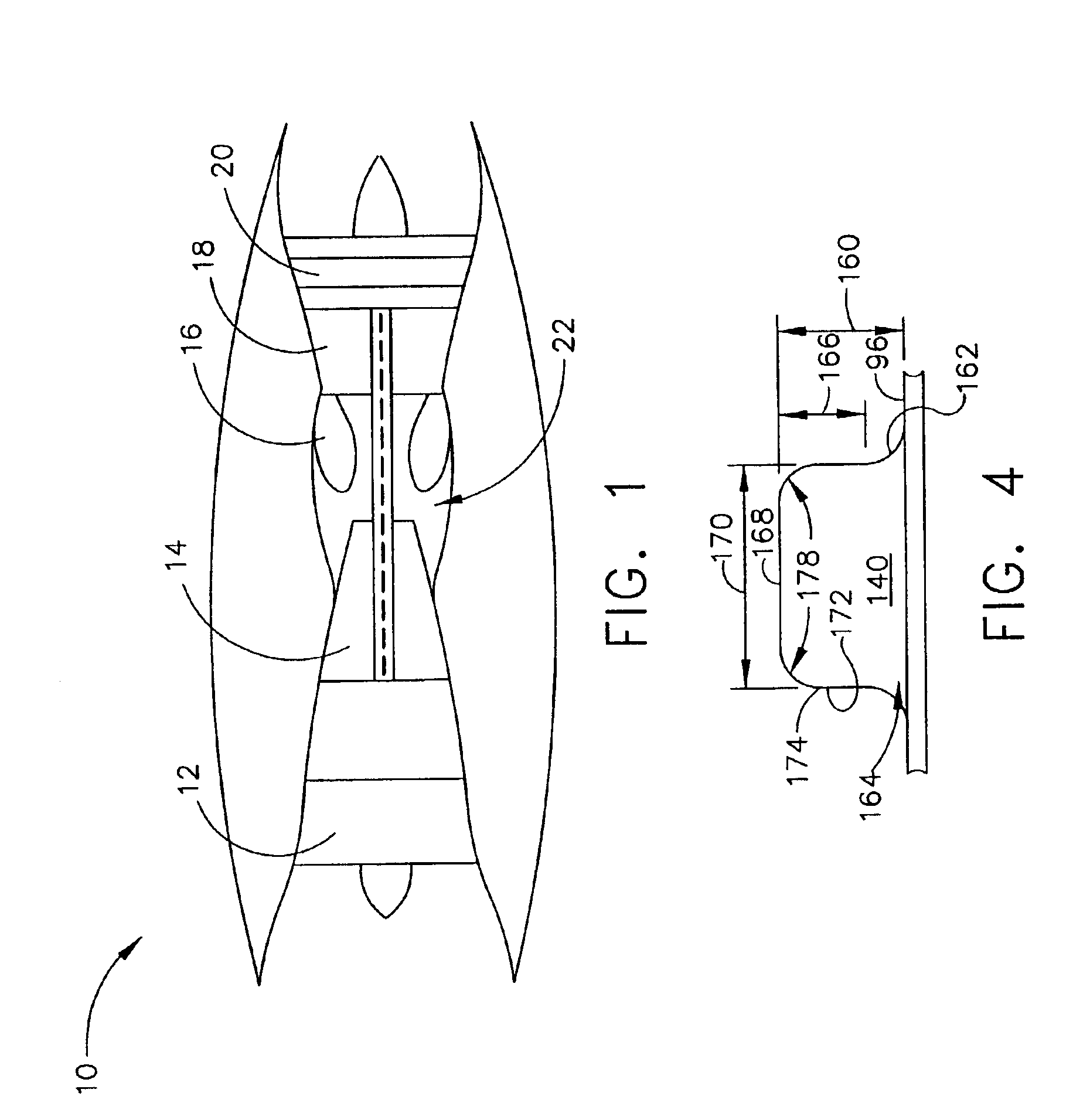
FIG. 1 is a schematic illustration of a gas turbine engine 10 including a low pressure compressor 12, a high pressure compressor 14, and a combustor 16. Engine 10 also includes a high pressure turbine 18 and a low pressure turbine 20. Combustor 16 includes an upstream side 22, and at least one dome (not shown). In one embodiment, the gas turbine engine is a GE-90 engine commercially available from General Electric Company, Cincinnati, Ohio.

In operation, air flows through low pressure compressor 12 and compressed air is supplied from low pressure compressor 12 to high pressure compressor 14. The highly compressed air is delivered to combustor 16. Airflow (not shown in FIG. 1) from combustor 16 drives turbines 18 and 20.

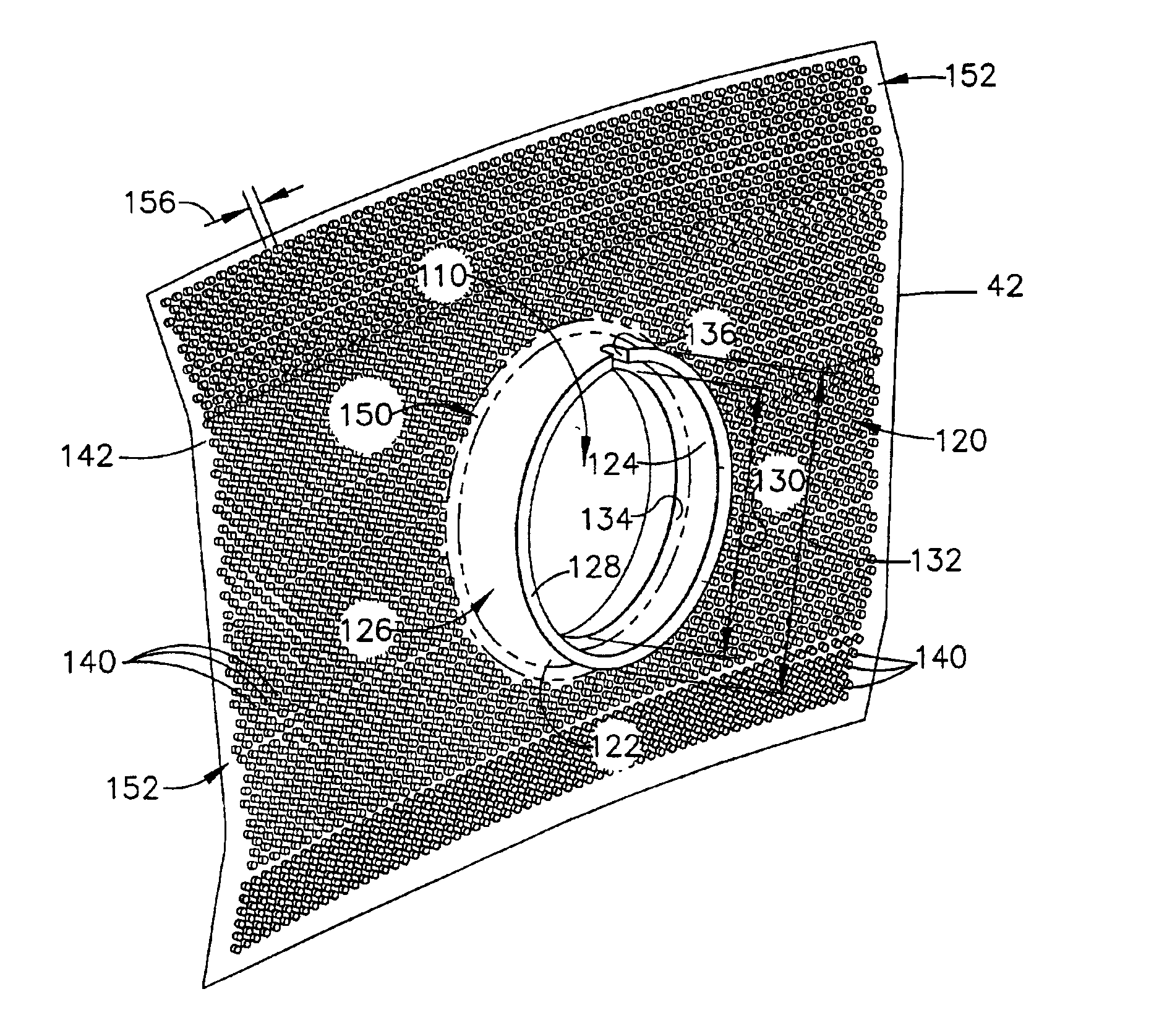
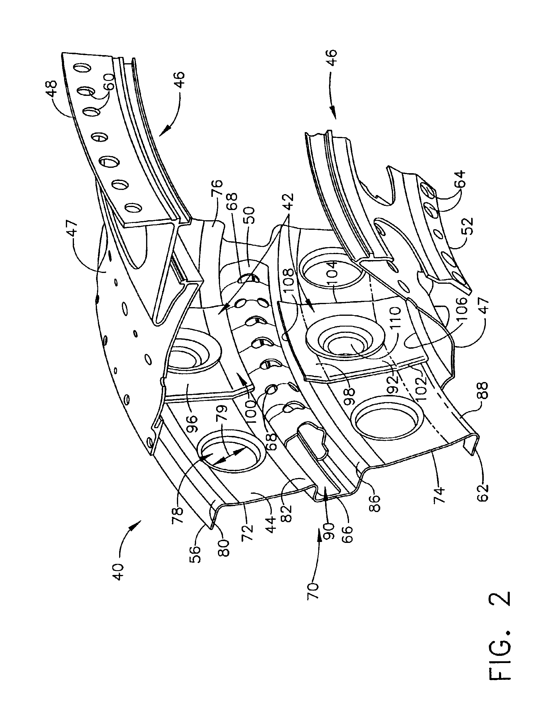
FIG. 2 is a partial perspective view of a deflector assembly 40 used with a combustor 16 (shown in FIG. 1) for a gas turbine engine, such as engine 10 shown in FIG. 1. Deflector assembly 40 is annular and includes a plurality of deflectors 42 and a spectacle plate 44. ...


PUM

PropertyMeasurementUnit
heightaaaaaaaaaa
radiusaaaaaaaaaa
distanceaaaaaaaaaa

Abstract

A combustor for a gas turbine engine includes a deflector assembly that enhances heat transfer from the combustor and minimizes low cycle fatigue stresses induced within the combustor. The deflector assembly includes a plurality of deflectors secured to a spectacle plate. Each deflector has tapered edges and includes a plurality of cylindrical projections extending outward from the deflector to facilitate heat transfer. The projections include rounded edges and are arranged in a high density pattern. The deflector is coated with a thermal barrier coating and a bondcoat to minimize exposure to hot combustion gases or flame radiation.

Description

BACKGROUND OF THE INVENTIONThis application relates generally to gas turbine engine combustors and, more particularly, to combustor deflectors.Combustors are used to ignite fuel and air mixtures in gas turbine engines. Known combustors include at least one dome attached to a liner defining a combustion zone. Fuel igniters are attached to the combustor in flow communication with the dome to supply fuel to the combustion zone. Fuel enters the combustor through a deflector attached to a spectacle plate. The deflector prevents hot combustion gases produced within the combustion zone from impinging upon the spectacle plate.Various types of deflectors are known and combustors typically include a plurality of deflectors. Known deflectors are rectangular-shaped and bordered with substantially square radial edges. The deflectors include a plurality of hemispherical projections to facilitate heat transfer from the deflector. The projections extend outward from the deflector and are hemispheri...

Claims


Application Information

Patent Timeline
Patent Type & Authority Patents(United States)
IPC IPC(8): F23R3/00F23R3/42C23C4/04F02C7/00F23R3/10
CPCF23R3/002F23R3/10F23R2900/00005Y10T29/49323Y10T29/49321Y10T29/4932Y10T29/49982Y10T29/49346Y10T29/49988
Inventor YOUNG, CRAIG D.LANMAN, EVA Z.MURACH, RONALD T.NAGARAJ, BANGALORE A.
Owner GENERAL ELECTRIC CO
Why Eureka
Try Eureka