Passive optical network backhaul for powerline communications

a passive optical network and powerline communication technology, applied in powerline communications applications, data switching networks, electric controllers, etc., can solve the problems of low overall cost of optical fiber cables and optical system equipment included in pons, low cost of installing the final segment of a broadband data communications service network, and low cost of installing this final segment of a broadband data communication service network. , to achieve the effect of high speed, easy and inexpensive coupling

Inactive Publication Date: 2005-01-18
ENIKIA
View PDF10 Cites 110 Cited by
  • Summary
  • Abstract
  • Description
  • Claims
  • Application Information

AI Technical Summary

Benefits of technology

In accordance with the present invention, a passive optical network / power line communications (“PON / PLC”) method and system provides for relatively quick, easy and inexpensive coupling of a passive optical network (“PON”) to existing, conventional electrical power conveying media to provide for distribution to an end user facility, such as a home or business, of high speed, broadband data communications services that are made available on the PON by high speed, broadband data communications service providers. The electrical power media can include low voltage, medium voltage and high voltage electrical power lines of existing, electrical power distribution networks.

Problems solved by technology

The proliferation of optical fiber cable installations, however, has not extended to a large number of end user facilities because of the high cost associated with installing optical fiber cable and associated optical signal equipment between an access point of an optical fiber cable data communications network and an end user facility, such as to the curb of or immediately outside or adjacent to a home or office building.
The overall cost of the optical fiber cables and the optical system equipment included in a PON is low relative to its high bandwidth and low loss signal transmission capabilities.
The cost of installing this final segment of a broadband data communications service network is relatively high, which has hindered the widespread deployment of high speed, broadband services using a PON.

Method used


Image

  • Passive optical network backhaul for powerline communications
  • Passive optical network backhaul for powerline communications
  • Passive optical network backhaul for powerline communications

Examples


Embodiment Construction

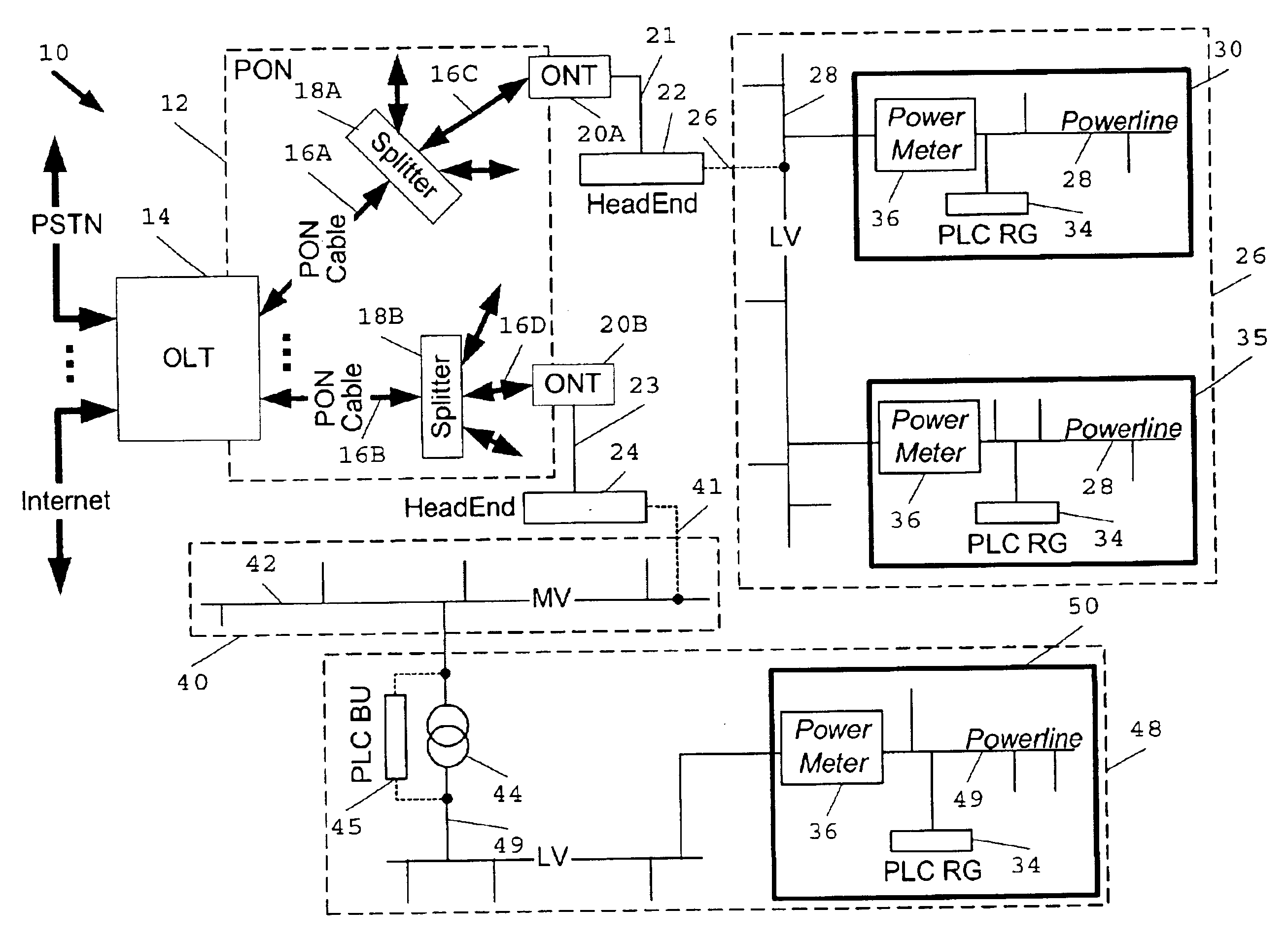
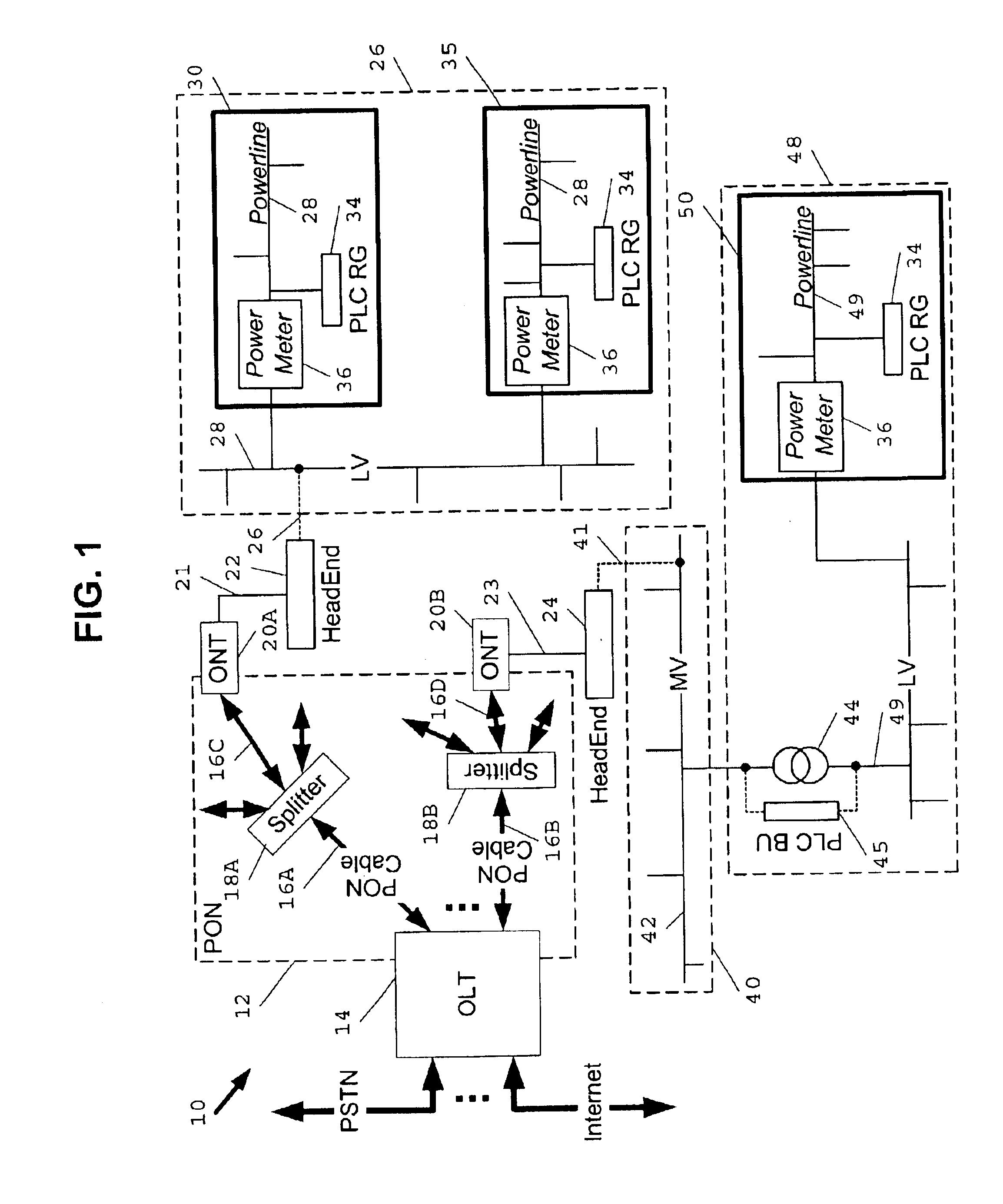
The present invention utilizes high speed PLC technology to provide for the delivery of high bandwidth, multi-media information, such as telephony, video-on-demand, broadcast TV, etc., available on a PON directly to an end user facility, such as a home or business, over conventional electrical power conveying media of an existing electrical power distribution network with relative ease and at a moderate installation cost.

FIG. 1 is a PON / PLC broadband data communications service network 10 in accordance with a preferred embodiment of the present invention. Referring to FIG. 1, the network 10 includes a passive optical network (“PON”) 12 containing an optical line termination (“OLT”) 14. The OLT 14 is coupled to broadband data communications service providers, such as a video server providing video-on-demand, a publicly switched telephone network (“PSTN”), an Internet service provider and a broadcast video and audio service provider, e g., CATV provider, etc., which are external to th...


PUM


Abstract

System, apparatus and method for connecting a passive optical network (“PON”) to a power line communications (“PLC”) network using a PLC HeadEnd installed at the PON to provide for distribution of high speed, broadband data communications services available on the PON to the PLC network using high speed, broadband PLC data signals. Where the PLC HeadEnd is installed on a medium voltage power distribution network, a PLC bypass unit is installed at a medium voltage/low voltage power transformer in the PLC network to provide PLC signal connectivity between the MV and LV networks. A PLC residential gateway is installed at each end user facility, such as a home or business, desiring broadband service available on the PON.

Description

FIELD OF THE INVENTIONThis invention relates to the field of data communications over conventional utility electric power conveying media, and more particularly to connecting passive optical networks (“PONs”) to existing, electric power distribution networks using power line communications (“PLC”) apparatus to make high speed, broadband data communications services on the PONs readily accessible on a PLC network.BACKGROUND OF THE INVENTIONHigh speed, broadband data communications service, such as the Internet, telephony, broadcast TV and video-on-demand, is typically delivered to homes and businesses over optical fiber cable, coaxial cable and copper wire, or various combinations thereof. Optical fiber is a most preferred media for delivery of broadband data communications services, because it has a much greater bandwidth capability than coaxial cable and copper wire. As a result, miles of optical fiber cable have been installed in an attempt to establish a high speed data communica...

Claims


Application Information

Patent Timeline
Patent Type & Authority Patents(United States)
IPC IPC(8): H04B3/54H04L12/28
CPCH04B3/54H04B3/542H04L12/2856H04L12/2885H04B2203/5445H04B2203/545H04B2203/5483Y04S20/228H04L2012/2843Y02B70/325H04B2203/5491Y02B70/30Y04S20/20
Inventor MANIS, CONSTANTINE N.LOGVINOV, OLEGDURFEE, LAWRENCE F.
Owner ENIKIA
Why Eureka
Try Eureka