Non-resonant four degrees-of-freedom micromachined gyroscope

a micro-machined gyroscope and non-resonant technology, applied in the direction of acceleration measurement using interia force, turn-sensitive devices, instruments, etc., can solve the problem of shifting in the resonant frequency, the most challenging type of gyroscope ever attempted, and the inability to achieve the most accurate measurement of the inertial sensor. , to achieve the effect of wide driving frequency range, favorable frequency response, and large oscillation amplitud

Inactive Publication Date: 2005-01-25
RGT UNIV OF CALIFORNIA
View PDF3 Cites 91 Cited by
  • Summary
  • Abstract
  • Description
  • Claims
  • Application Information

AI Technical Summary

Benefits of technology

Thus, less demanding active control strategies are required for operation under presence of perturbations. The fabricated prototype dual-mass gyroscopes successfully demonstrated a dramatically wide driving frequency range within where the drive direction oscillation amplitude varies insignificantly without any active control, in contrast to the conventional gyroscopes where the mass has to be sustained in constant amplitude oscillation in a very narrow frequency band. Mechanical amplification of driven mass oscillation by the sensing element was also experimentally demonstrated, providing large oscillation amplitudes, which is crucial for sensor performance.
The micromachined gyroscope of the invention does not operate at resonance. Two independently vibrating proof masses comprise the dynamical system. The first mass is forced to oscillate in the drive direction, and this forced oscillation is amplified by the second mass. The response of the second mass in the orthogonal sense direction is sensed as output. The resulting 4-degrees-of-freedom dynamic system has a more favorable frequency response, and operates in a wider frequency band with insignificant changes in the gain. The device has improved robustness against expected fabrication and packaging fluctuations, especially against damping variations due to ambient pressure.

Problems solved by technology

Thus expensive and bulky conventional inertial sensors will be eventually replaced by their micromachined counterparts without compromising performance.
Gyroscopes are probably the most challenging type of transducers ever attempted to be designed using MEMS technology.
However, the system is very sensitive to variations in system parameters causing a shift in the resonant frequency.
Under high quality factor conditions the gain is high, however the bandwidth is extremely narrow.
Fabrication imperfections are inevitable, and affect material properties and geometry of MEMS structures.
In addition, Young's Modulus of the structure is affected by deposition conditions.
Furthermore, during the operation time of these devices, fluctuations in the ambient temperature alter the gyroscope geometry together with structural properties, and pressure fluctuations affect the damping conditions, resulting in significant errors.

Method used


Image

  • Non-resonant four degrees-of-freedom micromachined gyroscope
  • Non-resonant four degrees-of-freedom micromachined gyroscope
  • Non-resonant four degrees-of-freedom micromachined gyroscope

Examples


Embodiment Construction

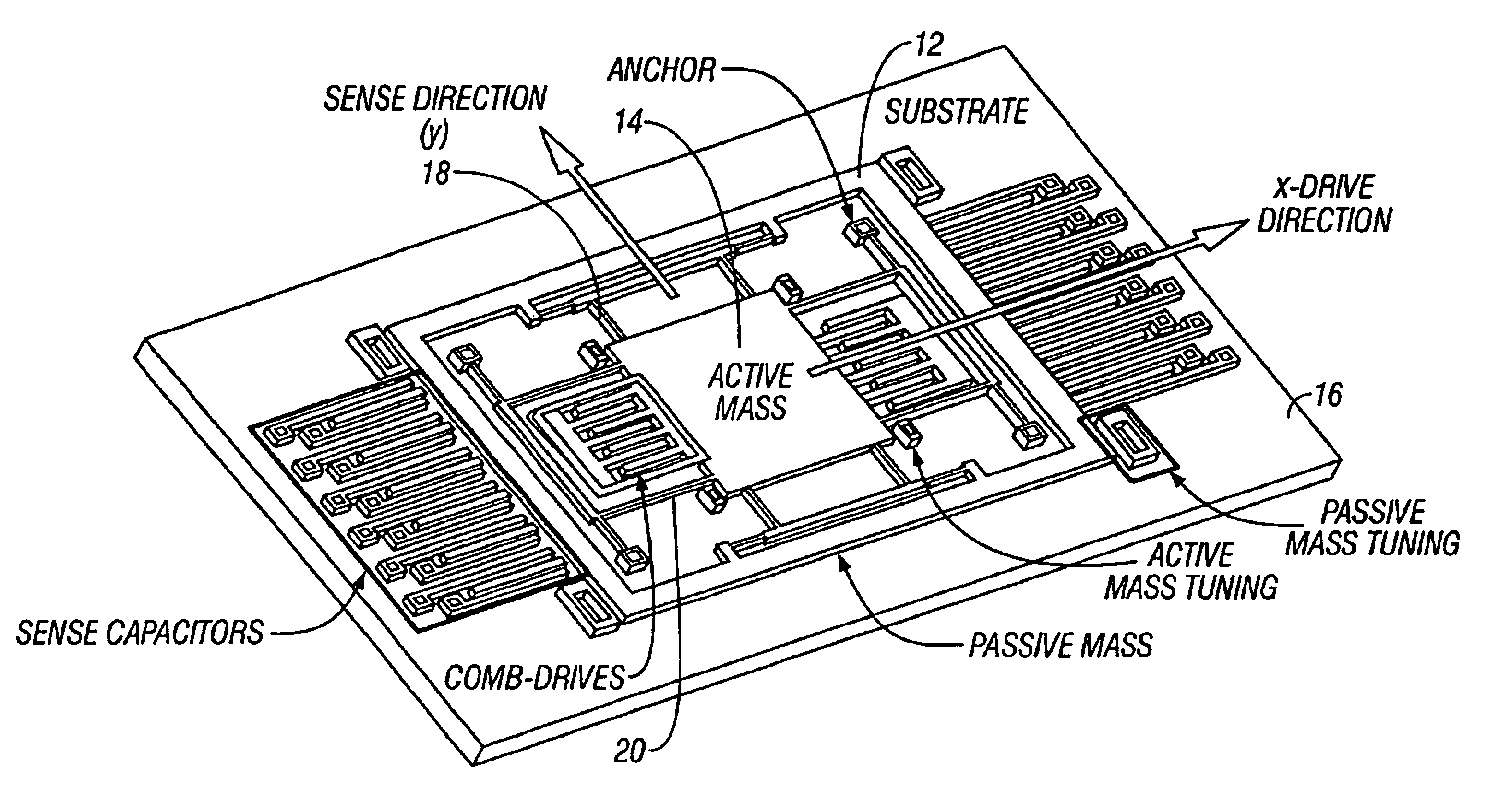
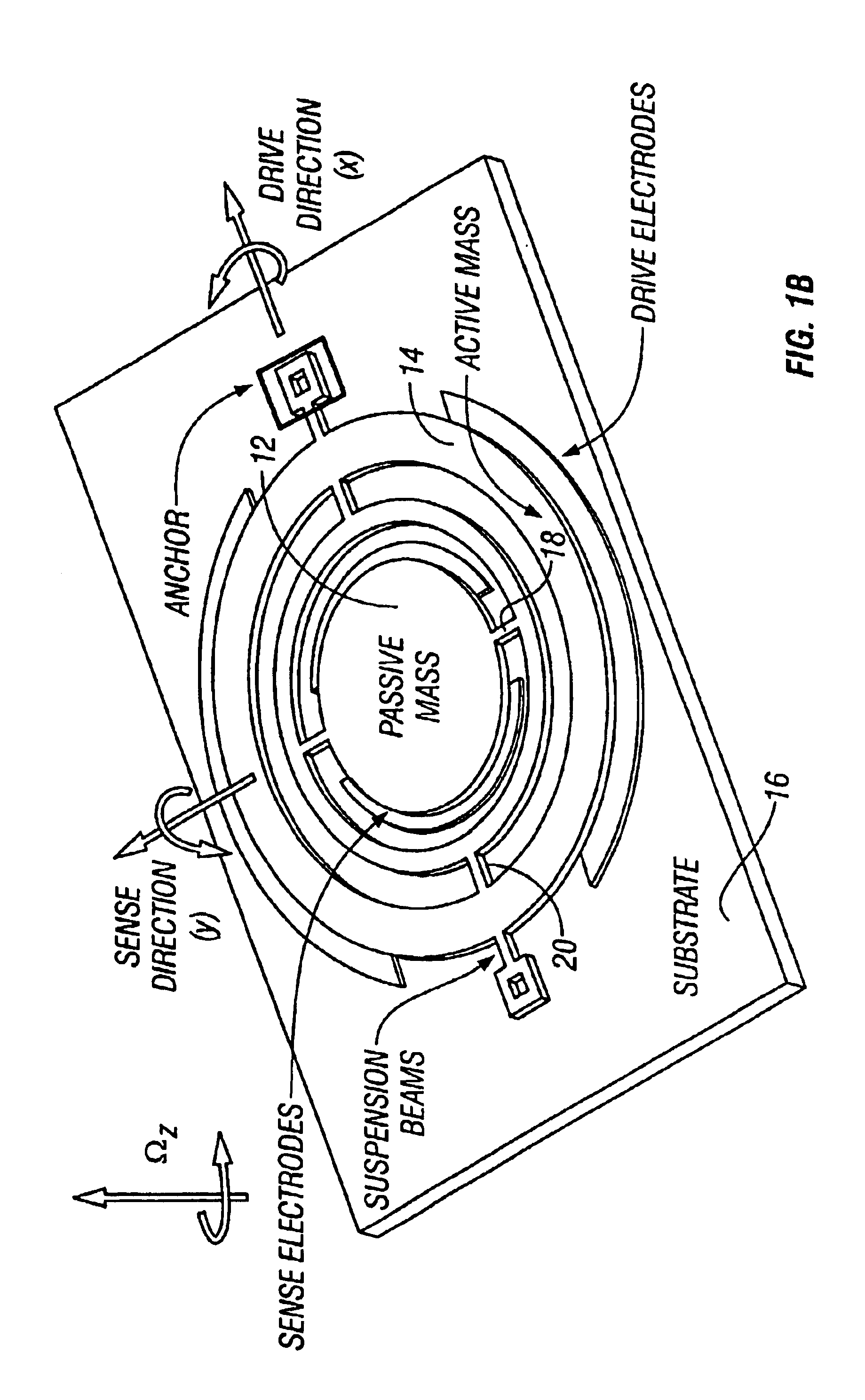
The conventional micromachined rate gyroscopes operate on the vibratory principle of a 2 degrees-of-freedom (DOF) system with a single proof mass suspended by flexures anchored to the substrate, which make the mass free to oscillate in two orthogonal directions, namely the drive and the sense directions. The proof mass is sustained in resonance in drive direction, and in the presence of an angular rotation, the Coriolis force proportional to the input angular rate is induced, exciting the proof mass in the sense direction. To achieve high gain, the drive and the sense resonant frequencies are typically designed to match, and the device is controlled to operate at the peak of their response curve. However, this resonance dependent approach results in high sensitivity to variations in system parameters. Only 1% shift in resonance frequency might produce over 20% error in the output signal gain, while major dynamical system parameters were observed to be likely to deviate by up to 15% ...


PUM


Abstract

A micromachined design and method with inherent disturbance-rejection capabilities is based on increasing the degrees-of-freedom (DOF) of the oscillatory system by the use of two independently oscillating proof masses. Utilizing dynamical amplification in the 4-degrees-of-freedom system, inherent disturbance rejection is achieved, providing reduced sensitivity to structural and thermal parameter fluctuations and damping changes over the operating time of the device. In the proposed system, the first mass is forced to oscillate in the drive direction, and the response of the second mass in the orthogonal direction is sensed. The response has two resonant peaks and a flat region between peaks. Operation is in the flat region, where the gain is insensitive to frequency fluctuations. An over 15 times increase in the bandwidth of the system is achieved due to the use of the proposed architecture. In addition, the gain in the operation region has low sensitivity to damping changes. Consequently, by utilizing the disturbance-rejection capability of the dynamical system, improved robustness is achieved, which can relax tight fabrication tolerances and packaging requirements and thus result in reducing production cost of micromachined methods.

Description

BACKGROUND OF THE INVENTION1. Field of the InventionThe invention is directed to the field of micromachined gyroscopes, and in particular to designs and methods with inherent disturbance-rejection capabilities.2. Description of the Prior ArtWith the advances in micromachining technologies, low cost, on-chip inertial micro-sensors are beginning to enter the market. Derived from the conventional integrated circuit (IC) fabrication technologies, micromachining processes allow mass-production of microstructures with moving bodies on a chip together with control and signal conditioning electronics. Thus expensive and bulky conventional inertial sensors will be eventually replaced by their micromachined counterparts without compromising performance. Likewise, micromachined gyroscopes could potentially provide high accuracy rotation measurements leading to a wide range of applications including navigation and guidance systems, automotive safety systems, and consumer electronics. Gyroscopes...

Claims


Application Information

Patent Timeline
Patent Type & Authority Patents(United States)
IPC IPC(8): B81B3/00G01C19/56
CPCB81B3/0062G01C19/5719Y10T74/1275
Inventor ACAR, CENKSHKEL, ANDREI M.
Owner RGT UNIV OF CALIFORNIA
Why Eureka
Try Eureka