Plate-like multiple antenna and electrical equipment provided therewith

a technology of plate-like multiple antennas and electrical equipment, which is applied in the direction of resonant antennas, polarised antenna unit combinations, protective materials radiating elements, etc., can solve the problems of antenna damage, increased manufacture costs of resulting products, and difficulty in satisfying antenna performance requirements

Inactive Publication Date: 2005-01-25
HITACHI CABLE
View PDF6 Cites 88 Cited by
  • Summary
  • Abstract
  • Description
  • Claims
  • Application Information

AI Technical Summary

Benefits of technology

nstitution of FIG. 32 has the same advantageous effects and the purposes as that of FIGS. 31(a), 31(b), and 31(c), and hence, a plate-like multiple antenna 10, which can correspond to two frequency bands of radio waves applied as in the above-described examples is realized.
The constitutions shown in FIGS. 31(a), 31(b), and 31(c) as well as FIG. 32 exhibit such a characteristic feature of a plate-like multiple antenna 10 according to the present invention that a combination of a length of the first radiation conductor 3 and that of on and after the third radiation conductor can be altered so as to obtain a predetermined excitation pattern and a predetermined directional pattern in respective frequencies applied.
A seventh example of the present invention is described in conjunction with FIGS. 33(a) and 33(b). FIGS. 33(a) and 33(b) shows each of plate-like multiple antennas 102 in the case where a third radiation conductor 5 is added to a part of a first radiation conductor 3 wherein a length of the first radiat...

Problems solved by technology

Particularly, an antenna for personal digital assistance required for downsizing involves a problem of a space for installing the antenna, and a problem of a demand for performance acting counter to restriction in an antenna volume with downsizing of the personal digital assistance itself.
Furthermore, the same problem arises in a dimension of antenna itself with introduction of an antenna inside a wall in a room or introduction of such antenna into personal computer, electric appliances (hereinafter referred simply to “electric appliance” in a lump) or the like in a wireless network concept in home, which has been actively studied recently.
The above-described problem is due to such a cause that an exclusive space must be separately maintained in the case where an exclusive antenna is to be housed in a cabinet or a main body casing (hereinafter referred simply to as “cabinet” in a lump) in personal digital assistance or electric appliances.
Moreover, with downsizing and weight reduction of products, an antenna itself is naturally required for downsizing and weight reduction thereof, so that it is difficult to satisfy required performance of the antenna.
As a result, there arises increase in manufactures' costs of the resulting products, and prolongation of a term for development, because of alteration of respective specifications, which have been heretofore employed.
In this manner, however, ther...

Method used


Image

  • Plate-like multiple antenna and electrical equipment provided therewith
  • Plate-like multiple antenna and electrical equipment provided therewith
  • Plate-like multiple antenna and electrical equipment provided therewith

Examples


example 1

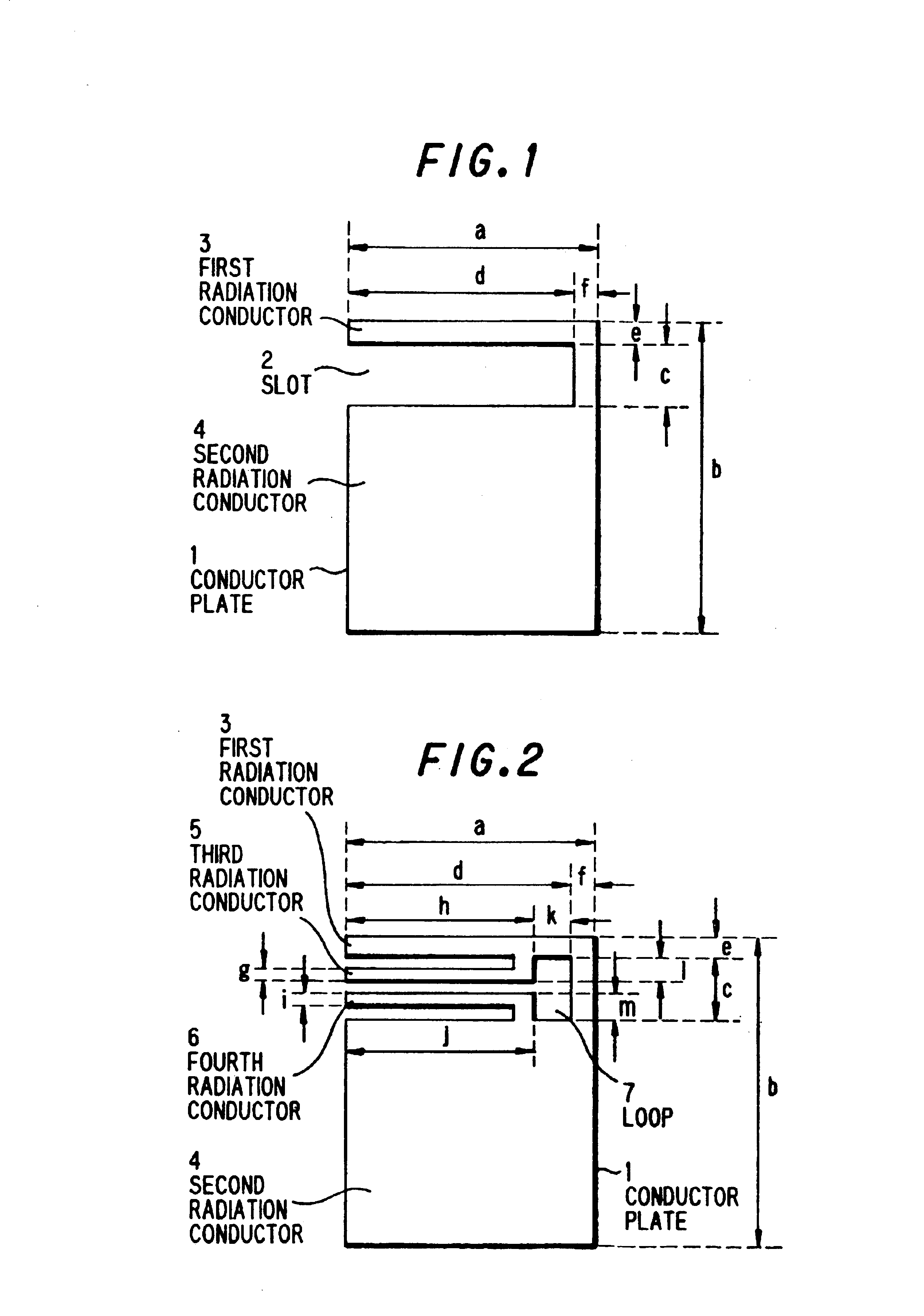
A first example of the present invention is described by referring to FIGS. 19, 20, and 2l wherein FIG. 19 shows a constitution, which uses a plate-like multiple antenna 101 according to the present invention obtained from the constitution of FIG. 14 as its basic model, wherein a first radiation conductor 3 has a length a1 obtained by adding a length d of a slot 2 to a width f of a conductor part joining the first radiation conductor 3 to a second radiation conductor 4, the length al of the first radiation is made to be substantially the same as that of a length b of the plate-like multiple antenna, and a width a of the plate-like multiple antenna is made to be wider than the length a1.

In this case, the length a1 is made to be about ¼ of a wavelength of one radio wave among a plurality of radio waves applied.

As shown in FIG. 19, since there is a portion 14 of difference Δ (hereinafter defined and referred to as “gap”) defined between the length a1 and the width a of the plate-like m...

example 2

A second example of the present invention is described by referring to FIGS. 22, 23, and 24 wherein FIG. 22 shows an example in which a dimension of the gap 14 is fixed, and only the length b in the plate-like multiple antenna 101 is changed in the example 1. In this case, a standing wave in the electric current (J2) 131 shown in FIG. 6 varies with changes in the length b of the plate-like multiple antenna 101, whereby it becomes possible that an electromagnetic field component in the first radiation structure, which is inclined in the slot 2 due to the gap 14, is much more inclined.

Hence, it has been found as shown in FIG. 23 that a directional pattern in the first radiation structure may be shifted in a direction where a gap 14 exists as in the case of example 1, and further a directional pattern in the first radiation structure can be suppressed in a direction where there is no gap 14.

Moreover, it has been found that a directional pattern in the second radiation structure is as s...

example 3

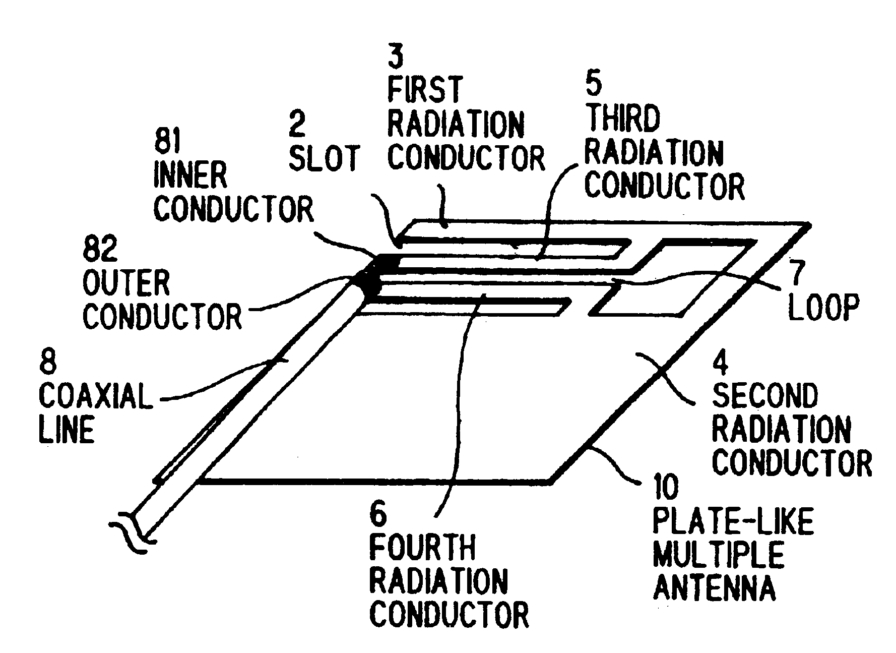
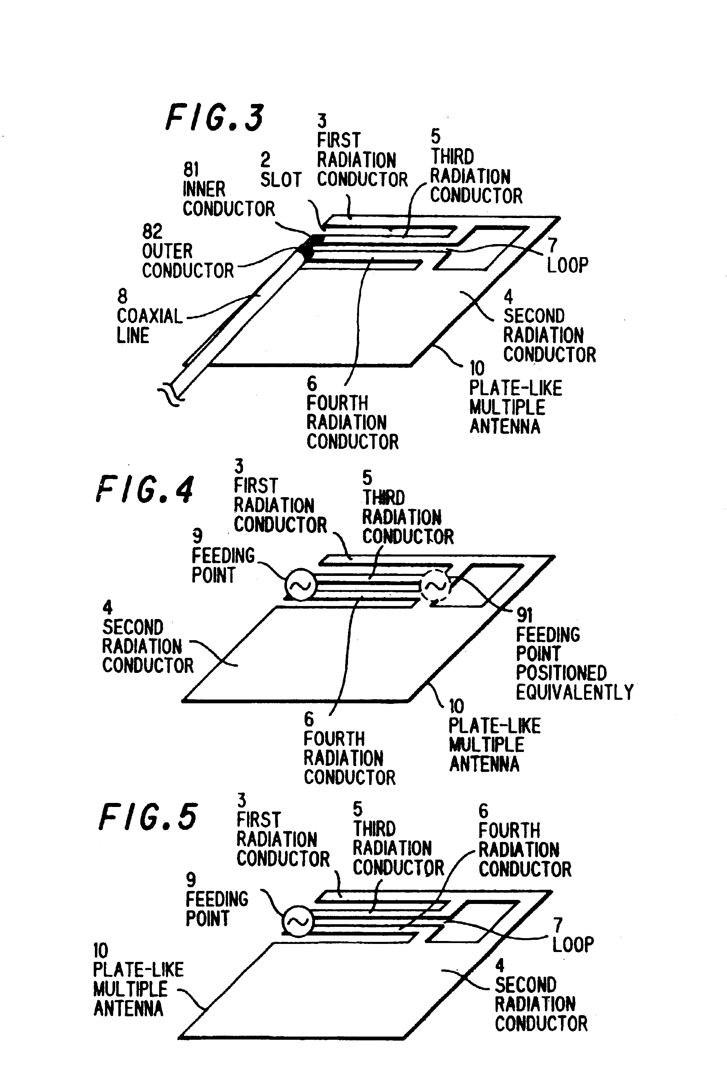
A third example of the present invention is described in conjunction with FIGS. 25 and 26 wherein FIG. 25 shows a constitution of a plate-like multiple antenna 102 according to the present invention in the case where a third radiation conductor 5 is added to a part of a first radiation conductor 3, a part of the third radiation conductor 5 is connected with an inner conductor 81 of a coaxial line 8, and further, apart of a second radiation conductor 4 is connected with an outer conductor 82 of the coaxial line 8, whereby power supply is implemented.

It is to be understood that these connecting positions are determined with taking constitutions of the first radiation structure and the second radiation structure by which radio waves in a plurality of frequency bands applied can be emitted as well as impedance matching of an antenna into consideration.

More specifically, a position at which the inner conductor 81 in the coaxial line 8 is to be connected with a part of the third radiation...


PUM


Abstract

A slot 2 is defined by notching a conductor plate 1, a first radiation conductor 3 and a second radiation conductor 4 are disposed by sandwiching the slot 2 as a boundary, a third radiation conductor 5 connected to either of the first radiation conductor 3 or the second radiation conductor 4 is provided in the slot 2, if necessary, on and after third radiation conductors, for example, a fourth and fifth radiation conductors connected to either of the first radiation conductor 3 or the second radiation conductor 4 are provided, a power is supplied in the slot by the use of conductor edges of at least two radiation conductors, if required, whereby two monopole antennas and slot antennas, which use respective electric currents on the first radiation conductor 3 and the second radiation conductor 4, are electrically formed, besides, antennas other than that described above are electrically formed by utilizing electric currents over on and after the third radiation conductors.

Description

BACKGROUND OF THE INVENTION1. Field of the InventionThe present invention relates to a plate-like multiple antenna composed of a conductor plate, which is compact and low-profile, besides, which may be easily housed in electric equipment such as personal digital assistance, and electrical appliances as well as in walls and the like; and the electrical equipment provided with such multiple antenna.2. Prior ArtIn recent years, downsizing for a variety of antennas for exclusive use in equipment including personal digital assistance, mobile computers, and the like (hereinafter referred simply to as “personal digital assistance” in a lump) except for large antennas for base station and satellite broadcasting has been actively made. Particularly, an antenna for personal digital assistance required for downsizing involves a problem of a space for installing the antenna, and a problem of a demand for performance acting counter to restriction in an antenna volume with downsizing of the perso...

Claims


Application Information

Patent Timeline
IPC IPC(8): H01Q1/22H01Q9/04H01Q5/00H01Q13/12H01Q13/10H01Q9/30H01Q21/24H01Q1/24H01Q1/36H01Q1/40H01Q5/10H01Q5/371H01Q7/00H01Q9/40H01Q13/08
CPCH01Q1/22H01Q9/30H01Q5/371H01Q13/12H01Q13/10
Inventor IKEGAYA, MORIHIKOSUGIYAMA, TAKAHIROSUZUKI, SHINICHIROTATE, HISASHI
Owner HITACHI CABLE
Why Eureka
Try Eureka