Seismic data acquisition method and apparatus

a seismic data and acquisition method technology, applied in direction finders, direction finders using ultrasonic/sonic/infrasonic waves, instruments, etc., can solve problems such as inability to bypass obstacles, acquisition channels may not be used to allow bypassing obstacles, and the coordinate values attributed to seismic data may be improperly moved

Inactive Publication Date: 2005-01-25
SCHLUMBERGER TECH CORP
View PDF12 Cites 78 Cited by
  • Summary
  • Abstract
  • Description
  • Claims
  • Application Information

AI Technical Summary

Problems solved by technology

However this is not always possible.
In the real world, many problems can occur that can generate errors when the position coordinates of the seismic station locations are matched with the acquisition channels of the seismic data acquisition system.
With complex lay-out in difficult terrain, some acquisition channels may not be used to allow the bypassing of obstacles.
A similar problem occurs if a cross-line or backbone cable is used to transmit seismic data from a seismic data cable to the recording equipment.
If the take-out at which the backbone cable is joined to the seismic data cable is not properly recorded and accounted for, it is possible to improperly shift the coordinate values attributed to the seismic data acquired by seismic sensors recorded using the seismic data cable.
This logic can easily be corrupted.
Errors generate major perturbations in the seismic processing, and the image quality of the processed seismic data can thereby be drastically decreased.
The quality of the seismic image obtained from the seismic data is also affected by other geometry problems.
When the actual sensor position coordinates differ from the sensor position coordinates that are assigned to the seismic data, the processing algorithms will often fail to correctly perform the intended data processing operation, and may in fact introduce noise or processing artifacts into the processed seismic data.
The non-optimum group pattern may also limit the performan...

Method used


Image

  • Seismic data acquisition method and apparatus
  • Seismic data acquisition method and apparatus
  • Seismic data acquisition method and apparatus

Examples


Embodiment Construction

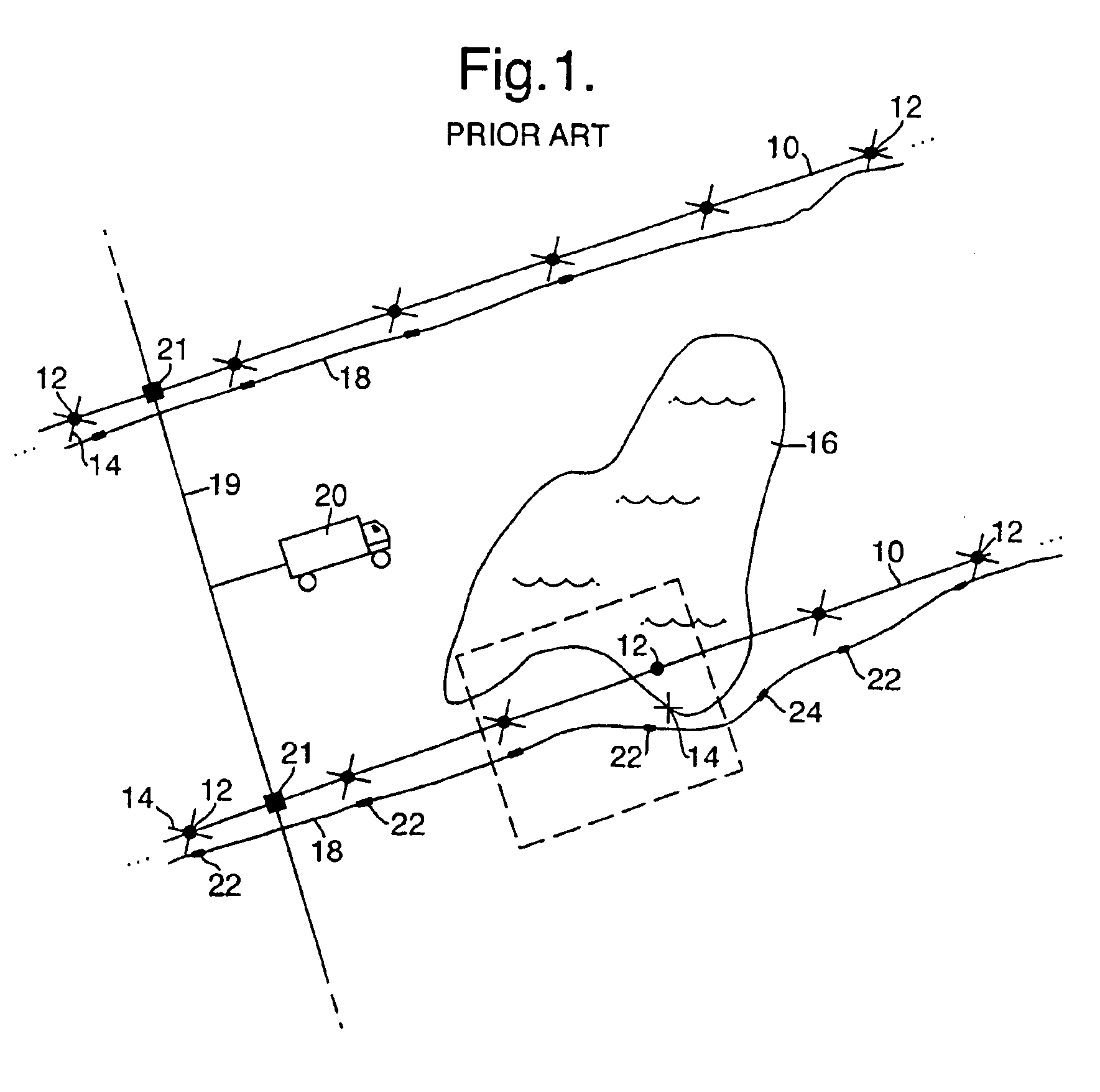
FIG. 1 shows a schematic view of a portion of a 3D seismic survey sensor lay-out scheme in a land environment. A plurality of parallel lines 10 are laid down over a particular geographic area and a number of pre-planned seismic survey station locations 12 are positioned at regular intervals along their lengths. It should be understood that only a portion of the entire 3D seismic survey sensor lay-out scheme is shown in FIG. 1. As discussed above, each line in a typical 3D seismic survey may be five kilometers in length and may including 100 stations. There may be between five to twenty active lines in a typical 3D seismic survey and the spacing between the lines may be on the order of 300 to 1000 meters or so.

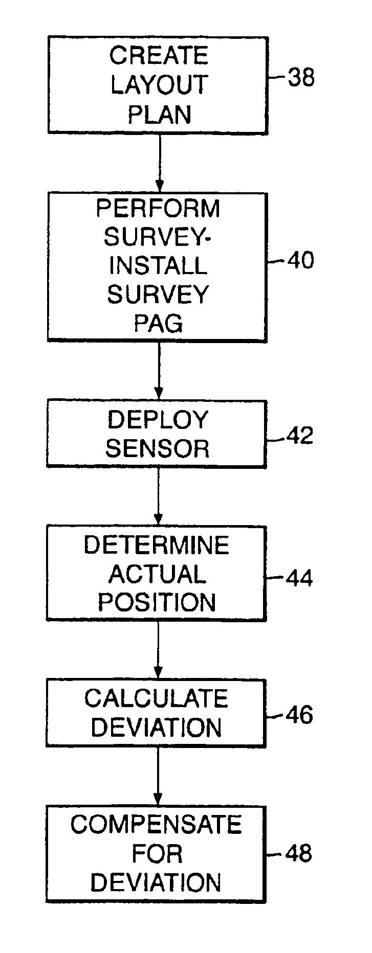
In the first phase of the seismic data acquisition process, a layout plan is created that determines where the lines 10 should be placed on the surface of the earth to obtain an “optimal” (in some geophysical sense) seismic image of the subsurface area of interest. In this firs...


PUM


Abstract

A method of acquiring seismic data adapted for a land or transition zone environment including placing a location identifier in a particular location, placing a seismic sensor near the location identifier, reading the location identifer using a seismic data cable, recording seismic data acquired by the seismic sensor using the seismic data cable, and assigning sensor position coordinates to the seismic data based on measured position coordinates of the location identifier. The invention also includes an apparatus adapted for seismic data acquisition in a land or transition zone environment including a location identifier, a seismic senor capable of being placed near the location identifier, a seismic data cable, means for reading the location identifier using the seismic data cable, means for recording seismic data acquired by the seismic sensor using the seismic data cable, and means for assigning sensor position coordinates to the seismic data based on measured position coordinates of the location identifier.

Description

BACKGROUND OF THE INVENTIONThe present invention re lates to a seismic data acquisition method and apparatus and in particular to a seismic data acquisition method and apparatus adapted for use in a land or transition zone environment th at provides for improved seismic sensor position determination, thereby reducing perturbation noise generated by inaccurate assignment of seismic sensor position coordinates to seismic data.Seismic data is collected to remotely sense subsurface geologic conditions, particularly in connection with the exploration for and production of hydrocarbon reserves, such as oil, natural gas, or coal. To gather seismic data, acoustic sources such as explosives or vibrators are used to produce an acoustic pulse that is transmitted through the subsurface geologic formations. Changes in acoustic impedance between different geologic layers cause a portion of the acoustic energy to be reflected and returned toward the earth's surface. These reflected signals are rec...

Claims


Application Information

Patent Timeline
IPC IPC(8): G01V1/00
CPCG01V1/003
Inventor ORBAN, JACQUES JOSEPH HENRIHATTELAND, KJELL
Owner SCHLUMBERGER TECH CORP
Why Eureka
Try Eureka