Electroluminescence display apparatus with opening in silicon oxide layer

Active Publication Date: 2005-02-01
SANYO ELECTRIC CO LTD
View PDF13 Cites 26 Cited by
  • Summary
  • Abstract
  • Description
  • Claims
  • Application Information

AI Technical Summary

Benefits of technology

According to the present invention, it is possible to provide an organic EL display apparatus with

Problems solved by technology

However, when there is a significant difference in the refractive indexes between adjacent layers among these layers, significant reflection is caused at the interface of these layers.
Consequently, in a structure in which light from the organic EL element is e

Method used


Image

  • Electroluminescence display apparatus with opening in silicon oxide layer
  • Electroluminescence display apparatus with opening in silicon oxide layer
  • Electroluminescence display apparatus with opening in silicon oxide layer

Examples


Example

Preferred embodiments of the present invention will be described in further detail with reference to the accompanying drawings.

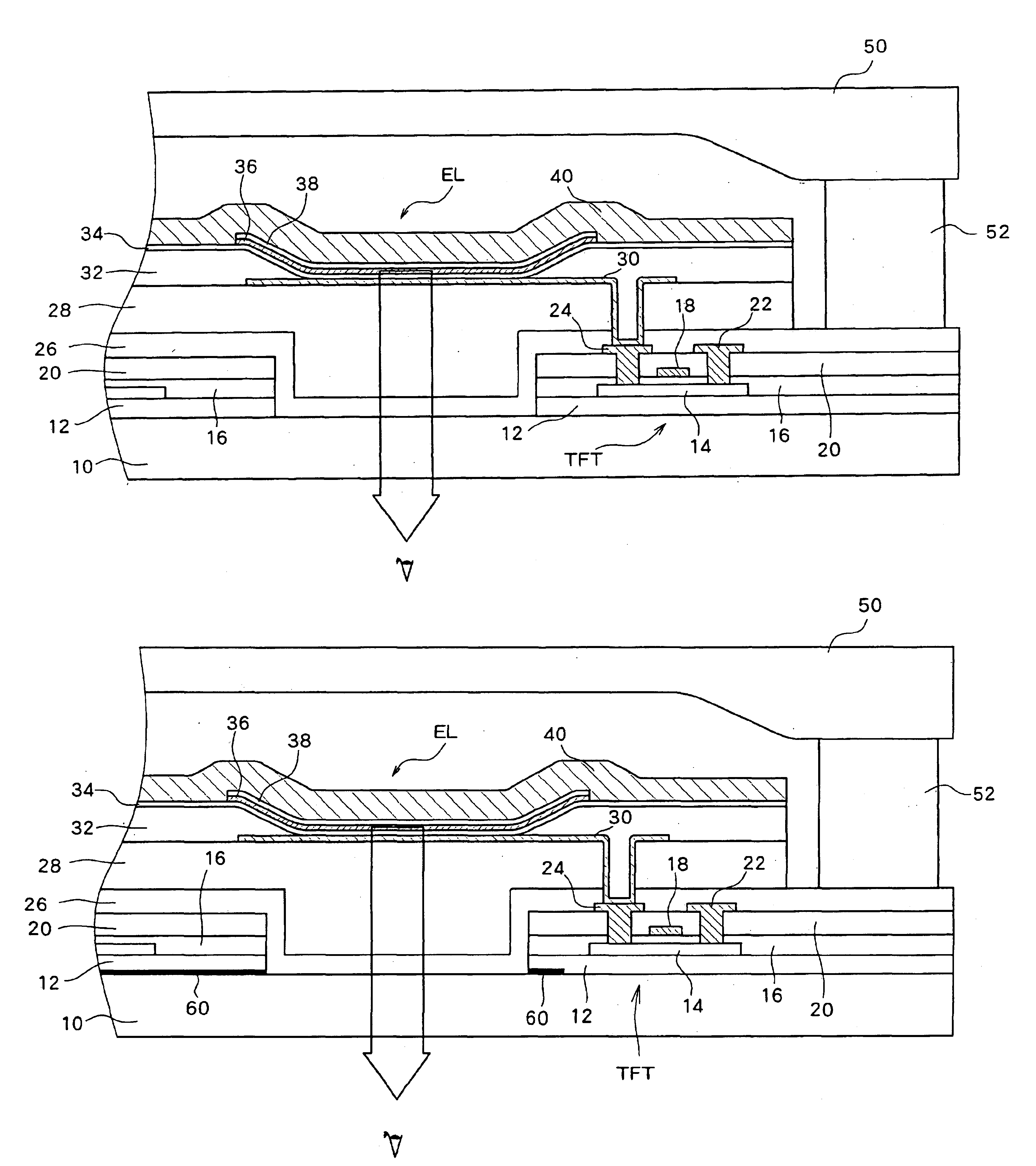
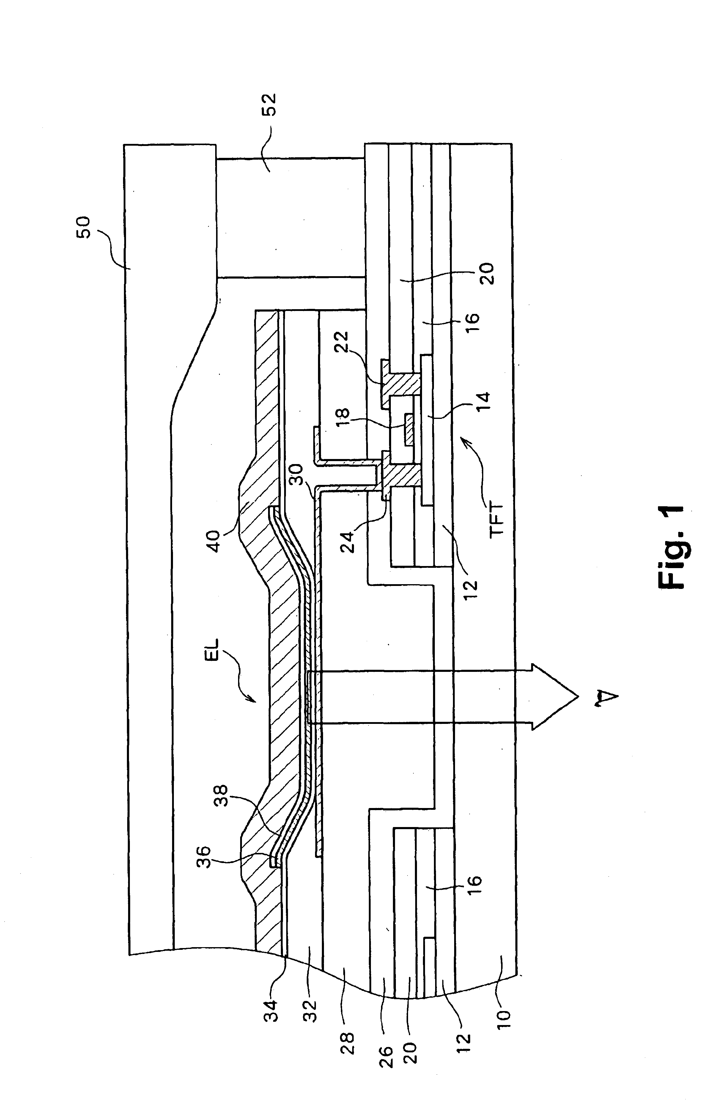
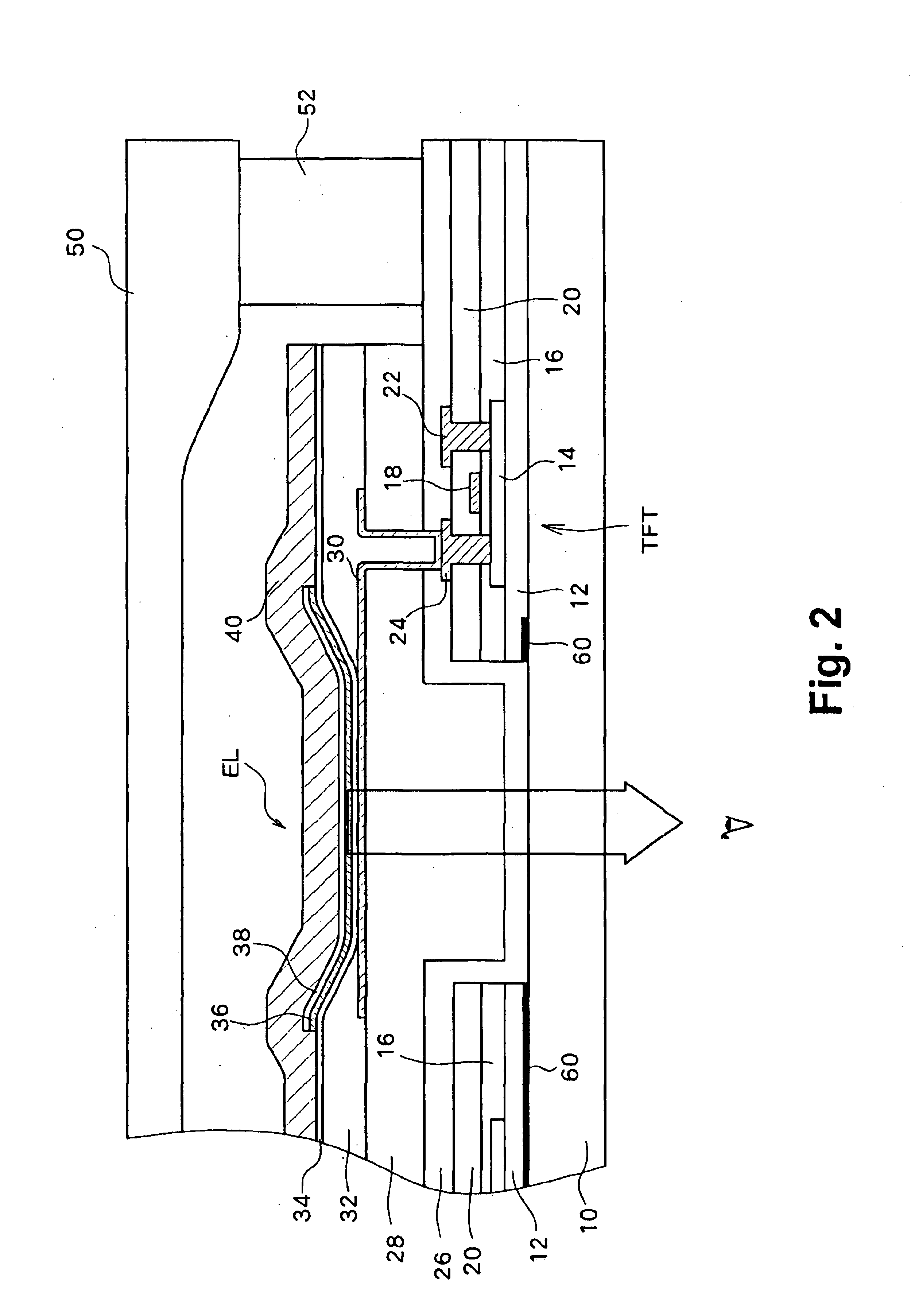
FIG. 1 is a cross sectional view showing a main portion (part of a pixel) of one preferred embodiment of the present invention. On a glass substrate 10, an insulating film 12 formed of two layers, an SiNx layer and an SiO2 layer, which are stacked in this order from the substrate side, is provided so as to prevent impurities from the glass substrate 10 from entering. On predetermined portions of the insulating film 12, a large number of thin film transistors are formed. Although in FIG. 1 a second TFT which is a thin film transistor for controlling current flowing from a power source line to the organic EL element is shown, a first TFT is also provided for each pixel for controlling accumulation of voltages (data signals) supplied from the data line in a storage capacitor. The second TFT is switched on in accordance with the voltage accumulated in the storag...


PUM


Abstract

An inter-layer insulating film and a gate insulating film which are positioned on the optical path of light from an organic EL element to be externally emitted, for example, located under a transparent electrode, are removed. Because SiO2 films having a refractive index which differs significantly from refractive indexes of other films are used for these films, there was a problem of light attenuation in these layers. Such light attenuation can be reduced by removing these layers located in the region through which light from the organic EL element passes.

Description

BACKGROUND OF THE INVENTION1. Field of the InventionThe present invention relates to an organic electrolulminescence (EL) element, and more particularly to prevention of attenuation of light to be externally emitted.2. Description of Related ArtOrganic EL display panels (organic EL display apparatuses) have conventionally been known as one example of flat display panels. Because, unlike liquid crystal display (LCD) panels, organic EL display apparatuses are self emissive and because organic EL display apparatuses are bright and clear flat display panels, their widespread use is very much expected.An organic EL display apparatus comprises a large number of organic EL elements arranged in a matrix, and employs these organic EL elements as pixels of a display. Such organic EL elements can be driven passively or actively, similar to LCDs, and, as is also the case with LCDS, active matrix displays are more preferable. More specifically, in active matrix displays, switching elements (typi...

Claims


Application Information

Patent Timeline
IPC IPC(8): H01L27/32H01L27/28H01L51/50H01L51/52H05B33/00
CPCH01L27/3244H01L51/5262H01L27/3258H01L51/5284H10K59/122H10K59/124H10K50/85H10K50/865H10K59/87H05B33/00H10K50/84
Inventor YONEDA, KIYOSHINISHIKAWA, RYUJISUZUKI, KOJIICHIKAWA, SHINJI
Owner SANYO ELECTRIC CO LTD
Why Eureka
Try Eureka