RF front end with reduced carrier leakage

a front end and carrier technology, applied in the direction of transmission, oscillation generator, electrically long antenna, etc., can solve the problems of carrier leakage, difficult to solve dc offset problem, delay in direct conversion receiver use in the wireless market, etc., to reduce carrier leakage and reduce dc offset at mixer output

Inactive Publication Date: 2005-02-01
GCT SEMICONDUCTOR INC
View PDF6 Cites 27 Cited by
  • Summary
  • Abstract
  • Description
  • Claims
  • Application Information

AI Technical Summary

Benefits of technology

Therefore, an object of the present invention is to provide a radio frequency (RF) front-end that reduces carrier leakage.
Another object of the present invention is to provide an RF front-end that reduces DC offset at the mixer output.

Problems solved by technology

Although it has a simply illustrated configuration, practical use of the direct conversion receiver in the wireless market has been delayed due to its inherent problems.
These problems relate to a direct current (D / C) component offset noise, which is proportional to the inverse value of the frequency (1 / f), and even-order distortion.
Of these, the DC offset problem is more difficult to solve, because there is a conflicting condition between DC offset measurement and DC offset correction.
The main cause of the DC offset results from carrier leakage.
Since the DC offset is located very close to DC, the measurement process of the DC offset requires too much time to perform for an offset cancellation technique based on averaging.
Also, the correction time for cancelling the DC offset tends to be long.
In wireless systems requiring a fast DC offset cancellation, most approaches are not feasible because of the above-described reasons.
However, the main difference between the related art heterodyne receiver and the illustrated design is the selection of the intermediate frequency (IF).
Since the signal isolation is not perfect in any RF front-end implementation, spectral leakage occurs through electromagnetic radiation, substrate-coupling, and parasitic coupling.

Method used


Image

  • RF front end with reduced carrier leakage
  • RF front end with reduced carrier leakage
  • RF front end with reduced carrier leakage

Examples


Embodiment Construction

Reference will now be made in detail to the preferred embodiments of the present invention, examples of which are illustrated in the accompanying drawings.

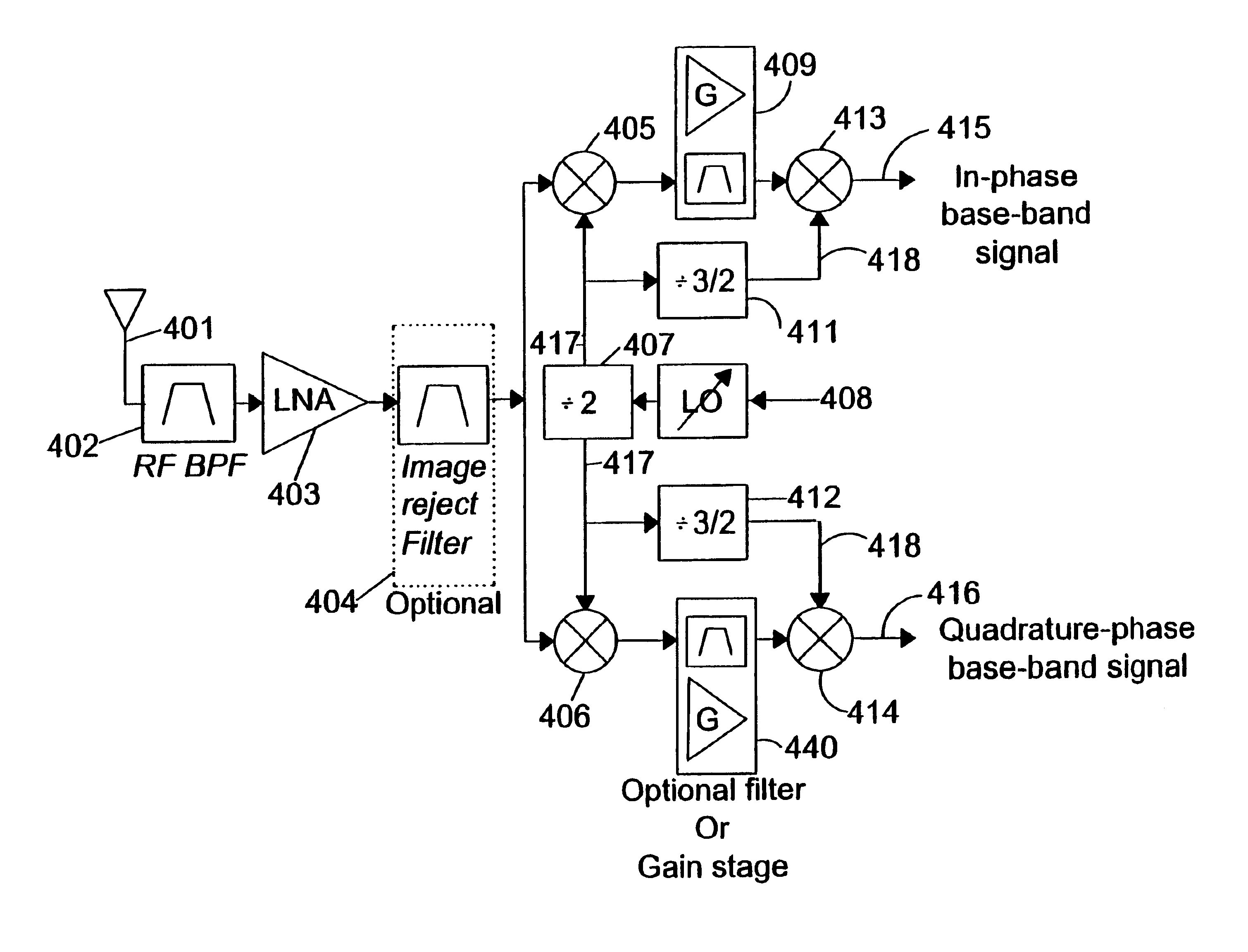
FIG. 4 illustrates a first preferred embodiment of an RF front-end for reducing or eliminating the DC offset. An antenna 401 provides a received radio frequency (RF) signal to RF bandpass filter (BPF) 402. RF BPF 402 filters the received RF signal to reduce or minimize the spectral energy of frequency components, outside the intended pass band, passed to a low noise amplifier (LNA) 403. LNA 403 amplifies the pass band signal, centered about the carrier frequency, that it receives from RF BPF 402 and passes the amplified signal to an optional image reject filter 404. Image reject filter 404 minimizes the spectral energy of the image signal received from LNA 403 and passes the filtered signal to both the in-phase first mixer 405 and the quadrature-phase first mixer 406. A variable frequency local oscillator (LO) 408 supplies a first...


PUM


Abstract

A method and apparatus that provide a frequency conversion in a radio frequency front-end are disclosed, including a frequency divider that divides an input signal frequency by a predetermined value to produce an output signal frequency; and a frequency mixer that mixes the output signal frequency with a carrier signal frequency to produce a converted signal frequency, which is substantially equal to a difference between the output signal frequency and the carrier signal frequency. The predetermined value and the input signal frequency are selected such that the carrier signal frequency is not substantially equivalent to an integer multiple of the output signal frequency. The method and apparatus can be used in a wireless communication receiver including wireless communication systems and wireless LAN systems.

Description

BACKGROUND OF THE INVENTION1. Field of the InventionThe present invention relates to a front-end of a wireless communication receiver and, more particularly, to a wide-band intermediate frequency (IF) radio receiver and a direct conversion radio receiver.2. Background of the Related ArtThe radio frequency (RF) front-end design in a wireless transceiver is perhaps the most important part of the receiver's design, because its performance in terms of the noise figure and linearity determines the overall performance of the receiver. There exist a number of architectures for implementing the radio transceiver. Two common ones are the heterodyne architecture and the homodyne or direct conversion architecture.As the demand for multi-mode and multi-band radio receivers grows, so too does the attention given to the direct conversion radio receiver. Although it has a simply illustrated configuration, practical use of the direct conversion receiver in the wireless market has been delayed due t...

Claims


Application Information

Patent Timeline
Patent Type & Authority Patents(United States)
IPC IPC(8): H04B1/28H04B1/52H04B1/50
CPCH04B1/28H04B1/525H04B1/16
Inventor SONG, EUNSEOKLEE, SEUNG-WOOKLEE, JEONG-WOOPARK, JOONBAELEE, KYEONGHO
Owner GCT SEMICONDUCTOR INC
Why Eureka
Try Eureka