Radio frequency guide wire assembly with optical coherence reflectometry guidance

a technology of optical coherence reflectometry and guide wires, which is applied in the direction of medical science, surgical instruments details, surgery, etc., can solve the problems of difficult to guide known guide wires through the body without risking damage, and the difficulty of guiding known guide wires through the body without substantial risk of damage or puncturing the artery wall,

Inactive Publication Date: 2005-02-08
SPECTRANETICS
View PDF21 Cites 155 Cited by
  • Summary
  • Abstract
  • Description
  • Claims
  • Application Information

AI Technical Summary

Problems solved by technology

Such plaque build-up restricts circulation and often causes cardiovascular problems, especially when the build-up occurs in coronary arteries.
However, it often is difficult to guide known guide wires through the body without risking damage.
For example, known guide wires typically cannot be easily advanced through partially or totally occluded arteries without substantial risk of damaging or puncturing the artery wall.
As the guide wire is advanced through the artery, it will encounter obstructions to advancement including plaque build-up or the artery wall itself.
However, known guide wires typically do not distinguish between plaque build-up and the artery wall.
An operator may therefore incorrectly identify an obstruction as plaque build-up and attempt to push the guide wire through the obstruction, resulting in injury or puncture of the artery wall.
Even if the direction of the artery is known, often it is not possible to pass a guide wire through the occlusion because the lesion is too resistant or it is a refractory lesion.

Method used


Image

  • Radio frequency guide wire assembly with optical coherence reflectometry guidance
  • Radio frequency guide wire assembly with optical coherence reflectometry guidance
  • Radio frequency guide wire assembly with optical coherence reflectometry guidance

Examples


Embodiment Construction

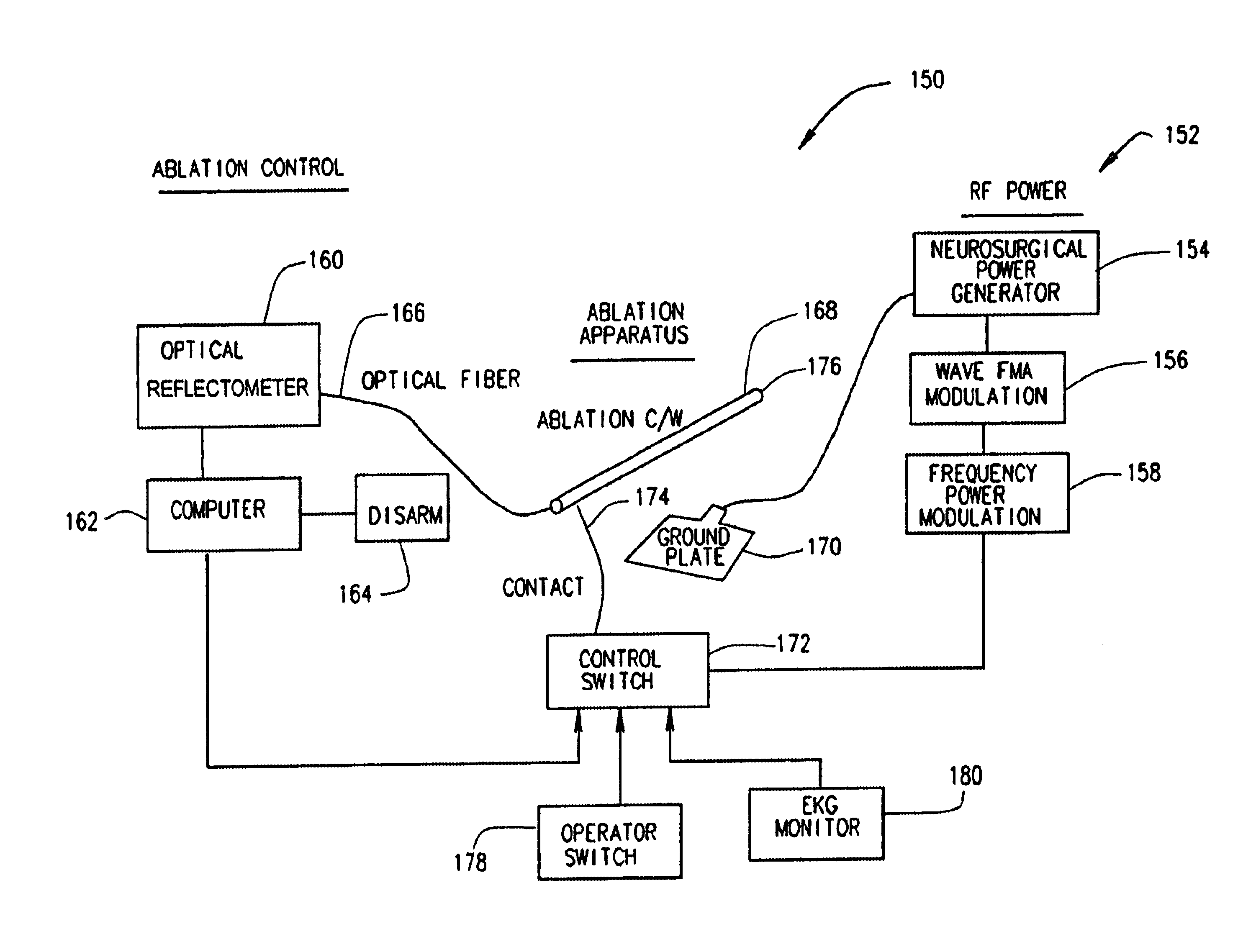
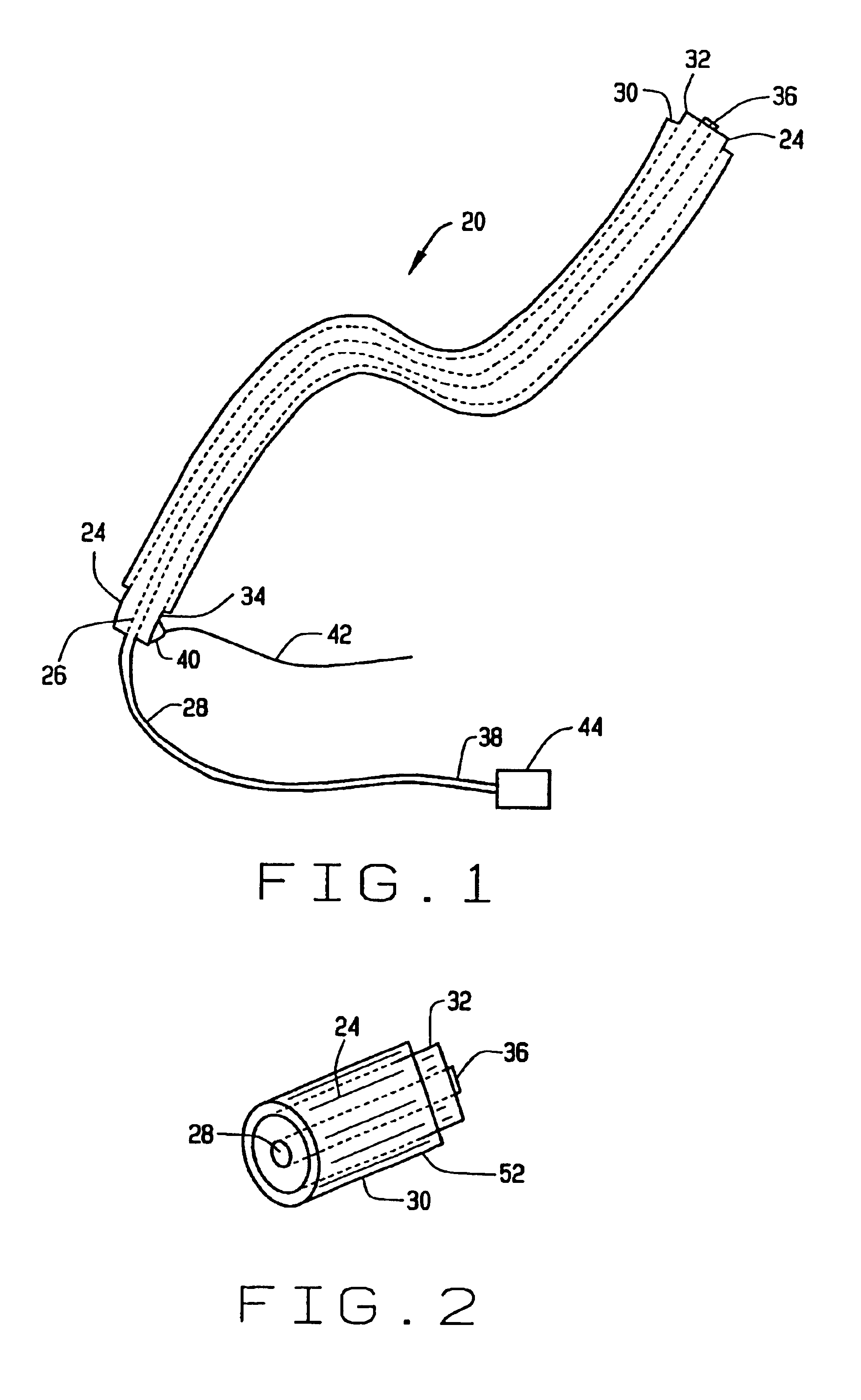
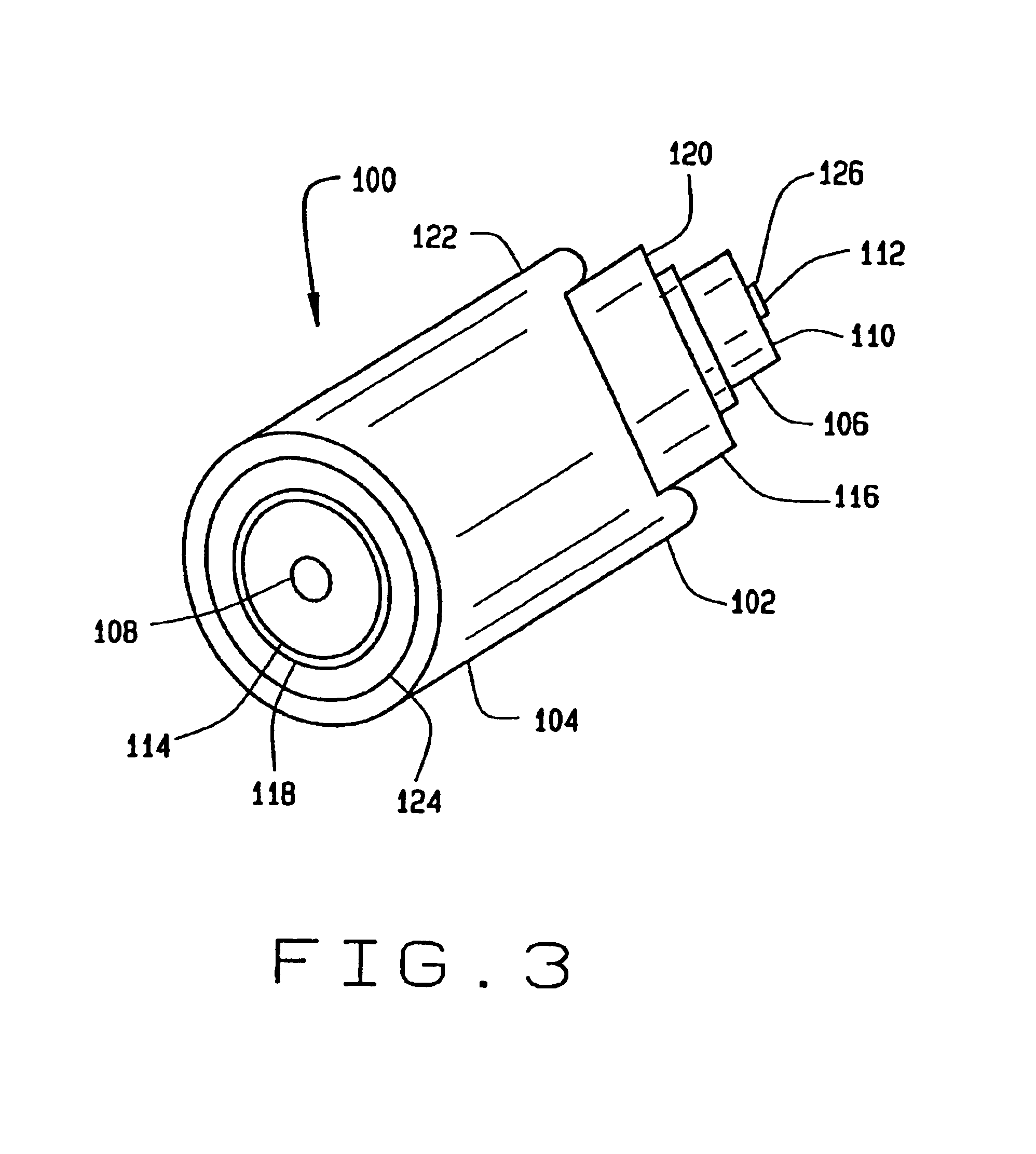
FIG. 1 illustrates one embodiment of a guide wire assembly 20. In one application, guide wire assembly 20 utilizes optical coherence reflectometry (OCR) to control an RF ablation feature implemented using guide wire assembly 20. Referring specifically to guide wire assembly 20, there is included a metal guide wire 24 having a cylindrical bore 26 therethrough. An optical fiber 28 is located within bore 26 of guide wire 24. Guide wire assembly 20 is configured to be inserted into a body passage (not shown) such as a blood vessel. Guide wire assembly 20 further includes an insulation coating 30 extending over guide wire 24 as further described below. Guide wire 24 has a distal end 32 and a proximal end 34 and optical fiber 28 also includes a distal end 36 and a proximal end 38. As referred to herein, “distal end” refers to an end first inserted into the body passage and “proximal” refers to an end opposite the “distal end”. Distal ends 32 and 36 are positioned within a blood vessel (no...


PUM

PropertyMeasurementUnit
frequencyaaaaaaaaaa
diameteraaaaaaaaaa
diameteraaaaaaaaaa

Abstract

A guide wire assembly includes a guide wire, an optical fiber, and an insulating coating. The guide wire has a distal end, a proximal end, and a bore extending through the wire between the distal and proximal ends. The an optical fiber also includes a distal end and a proximal end and is located within the bore of the guide wire. The optical fiber extends at least between the distal and proximal ends of the guide wire. The insulating coating is around an outside diameter of the guide wire, and is applied such that the distal ends of the guide wire and optical fiber are exposed.

Description

BACKGROUND OF THE INVENTIONThis invention relates generally to medical guide wires and catheters and more particularly, to guiding assemblies and guiding methods for guide wires.Disease processes, e.g., tumors, inflammation of lymph nodes, and plaque build-up in arteries, often afflict the human body. As one specific example, atherosclerotic plaque is known to build up in the walls of arteries in the human body. Such plaque build-up restricts circulation and often causes cardiovascular problems, especially when the build-up occurs in coronary arteries.To treat such disease, it often is necessary to guide a medical device to the diseased site, and then use the medical device to treat the diseased area. Commonly a guide wire is used to help guide other treatment devices. A guide wire typically is required to properly position a catheter in an artery. The guide wire is advanced and forms a path, through the artery and region of plaque build-up. The catheter or other device such as a ba...

Claims


Application Information

Patent Timeline
Patent Type & Authority Patents(United States)
IPC IPC(8): A61B18/14A61B18/20A61B18/22A61B17/00A61B1/00A61B18/12A61L31/00A61M25/01
CPCA61B18/1492A61B18/22A61B2018/144A61B2017/00247A61B2018/00392A61B2017/00061
Inventor WINSTON, THOMAS R.NEET, JOHN M.
Owner SPECTRANETICS
Why Eureka
Try Eureka