

Interferometers for optical coherence tomography and reflectometry
a technology of optical coherence tomography and reflectometer, which is applied in the field of optical coherence tomography and reflectometry interferometers, can solve the problems of limiting the depth of oct imaging, the requirement of singly scattered gating practically limits the oct imaging, and the difficulty of optical imaging in scattering media such as biological tissue, etc., and achieves low coherence
- Summary
- Abstract
- Description
- Claims
- Application Information
AI Technical Summary
Benefits of technology
Problems solved by technology
Method used
Image

Examples
embodiment # 1
Embodiment #1
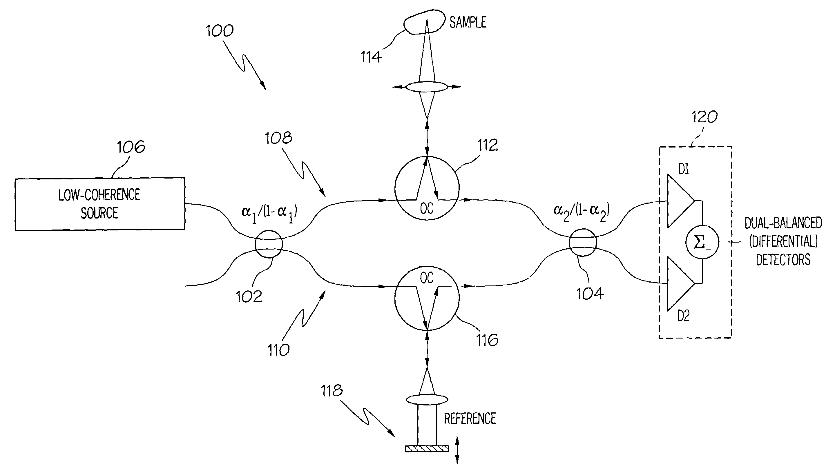
[0041]The embodiment illustrated in FIG. 6 uses an interferometer configuration 100 similar to the Mach-Zehnder illustrated in FIG. 5, except that both couplers or beamsplitters 102 and 104 may be unbalanced. In FIG. 6, an unbalanced singlemode coupler 102 splits light from the source 106 and sends most of the source light power to the sample arm 108 of the interferometer 100. The splitting ratio of the unbalanced coupler 102 is selected such that the amount of power directed into the reference arm 110 is within the suitable range for shot-noise limited detection. An optical circulator 112 directs the sample arm light onto the sample 114, and directs light returning from the sample into a second singlemode coupler 104, which in general may also be unbalanced. In the reference arm 110, a second optical circulator 116 directs reference arm light onto a variable reference delay element 118, and directs light returning from the delay 118 into the other input port of second ...
embodiment # 2
Embodiment #2
[0048]The interferometer 130 illustrated in FIG. 7 is similar to that illustrated in FIG. 6, except that the expense of one of the optical circulators is avoided by use of a transmissive delay element 132 rather than a reflective reference arm delay. The transmissive delay element 132 could be similar to element 70 illustrated in FIG. 5. All other advantages of the first embodiment are preserved. The expression for the signal-to-noise ratio in the case of α2=0.5 (dual-balanced detection) is the same as equation (3), in which case the expression for the optimal first coupler splitting ratio is:
[0049]α1=2PminP0Rr(7)
Under the assumptions that Pmin=10 μW, P0=10 μW, Tc0.85, and Rr=0.9, the optimal value of the first coupler is then α1=0.0022, and the corresponding signal-to-noise ratio advantage over conventional OCDR / OCT is a factor of 2.88 (or 4.59 dB), which is identical to the dual-detector version of embodiment #1. The expression for the signal-to-noise ratio in the c...
embodiment # 3
Embodiment #3
[0051]The interferometer 140 illustrated in FIG. 8 is also similar to the first embodiment of FIG. 6, except that interferometer 140 avoids the additional expense of one optical circulator while still using a reflective reference delay 118. This embodiment preserves all of the advantages of the first embodiment, except that the gain in dynamic range as compared to the conventional system is slightly less, because the optimal value of the first coupler 102 splitting ratio is somewhat smaller than in embodiment #1 in order to compensate for the small amount of reference arm power which is returned to the source 106 rather than placed on a detector. Interferometer 140 will be the preferred one when a slight loss in efficiency is worth the savings of the cost of one optical circulator.
[0052]If the splitting ratio of the second beamsplitter 104 in interferometer 140 is chosen to be 50 / 50 (i.e., α2=0.5), then equal powers are incident on each of the dual detectors D1 and D2, ...
PUM
 Abstract
Description
Claims
Application Information