Hybrid valve apparatus and method for fluid handling

Inactive Publication Date: 2005-02-08
UT BATTELLE LLC +1
View PDF55 Cites 53 Cited by
  • Summary
  • Abstract
  • Description
  • Claims
  • Application Information

AI Technical Summary

Benefits of technology

Accordingly, at no time are the aspiration actuator or the dispensing actuator both in fluid communication with the sample path when the valve assembly is in either the aspiration or dispensing condition. This arrangement is highly beneficial in that contamination of the dispensing actuators can be eliminated by isolating the aspiration paths and dispensin

Problems solved by technology

Reduced volumes can lower costs by an order of magnitude but conventional liquid-handling devices fail at the required volumes.
The rate-limiting hardware is low volume liquid transfer technology that is robust and scalable for compounds of interest.
Problematic to these devices is plugging of orifices and scalability.
While this printing technology is capable of low-volume, acc

Method used


Image

  • Hybrid valve apparatus and method for fluid handling
  • Hybrid valve apparatus and method for fluid handling
  • Hybrid valve apparatus and method for fluid handling

Examples


Embodiment Construction

While the present invention will be described with reference to a few specific embodiments, the description is illustrative of the invention and is not to be construed as limiting the invention. Various modifications to the present invention can be made to the preferred embodiments by those skilled in the art without departing from the true spirit and scope of the invention as defined by the appended claims. It will be noted here that for a better understanding, like components are designated by like reference numerals throughout the various figures.

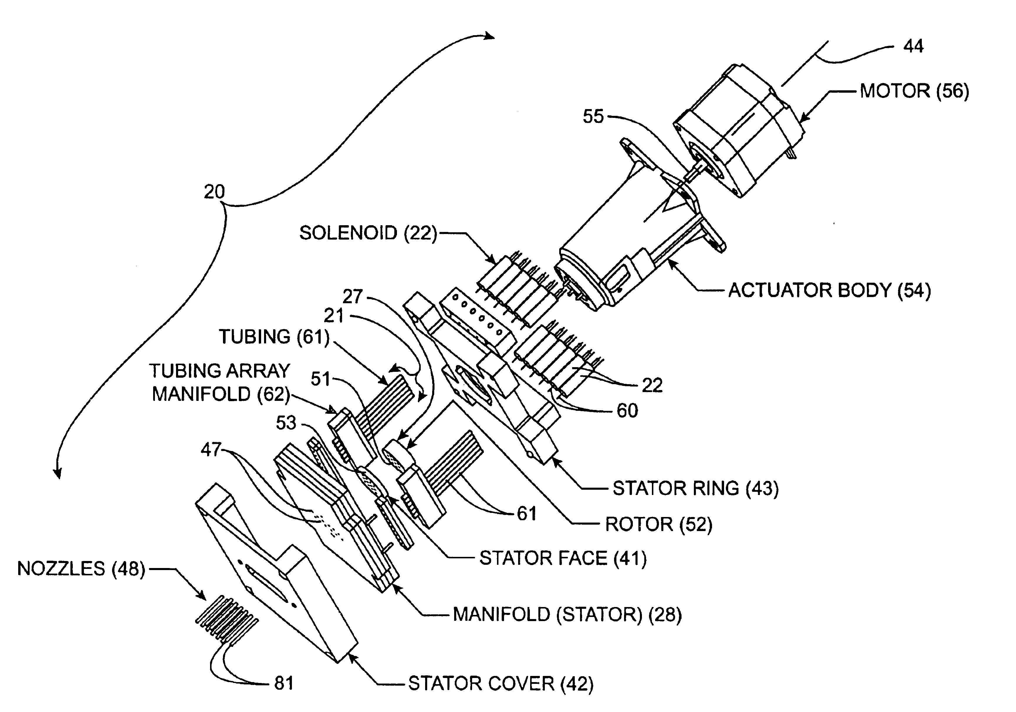
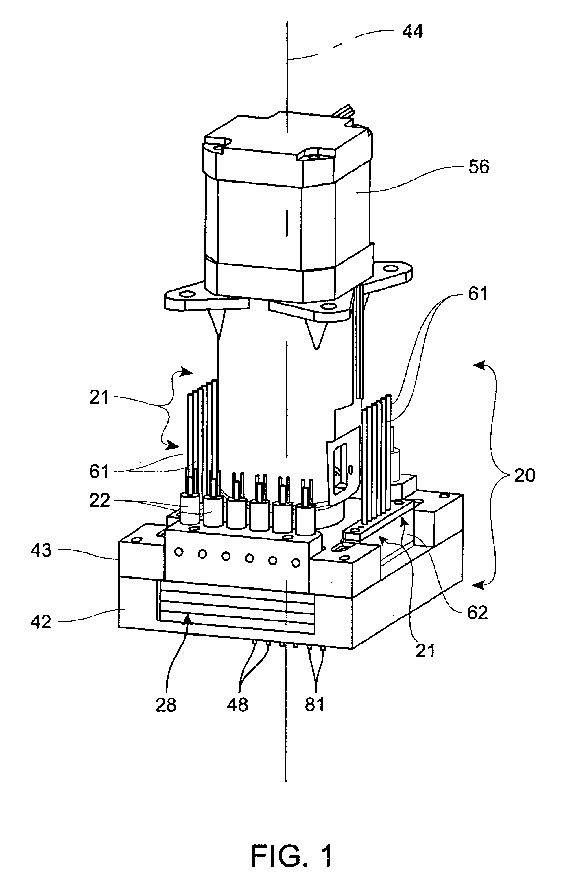
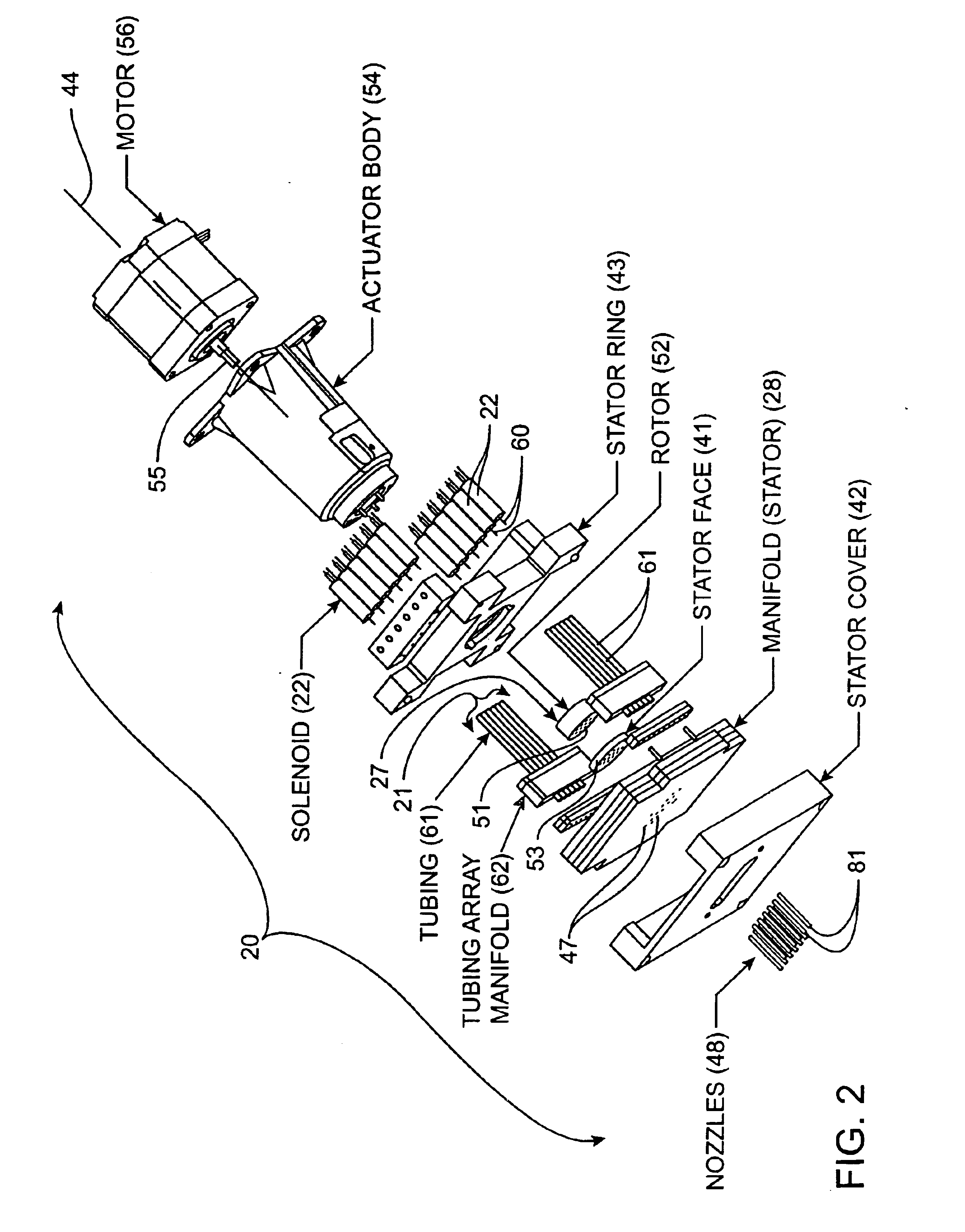
Referring now to FIGS. 1-6, 15 and 16, a hybrid valve apparatus, generally designated 20, is provided for use with an aspiration source 21 and a dispensing source 22 to transfer sample or reagent fluid from a reservoir 23 to a test site 25 on a substrate surface 26. Broadly, the hybrid valve apparatus 20 includes a valve assembly 27 (FIGS. 15 and 16) movable between an aspiration condition (FIGS. 5, 9 and 10) and a dispensing condition (...


PUM


Abstract

A hybrid valve apparatus for use with an aspiration actuator and a dispensing actuator to transfer fluid from a reservoir to a test site on a substrate surface. The hybrid valve includes a valve assembly movable between an aspiration condition and a dispensing condition, and a manifold device coupled to the valve assembly. The manifold device includes a fluid aspiration conduit having a first aspiration port in fluid communication with the aspiration actuator. On an opposite end of the aspiration conduit is a second aspiration port in selective fluid communication with the valve assembly to selectively aspirate a liquid sample slug from the reservoir into a discrete sample path when the valve assembly is in the aspiration condition. The manifold device further includes a fluid dispensing conduit having a first dispensing port in fluid communication with the dispensing actuator, and a second dispensing port in selective fluid communication with the valve assembly. When the valve assembly is in the dispensing condition, the sample path is fluidly coupled to the dispensing actuator to selectively dispense at least one droplet of the liquid sample slug therefrom, while simultaneously being out of fluid communication with the aspiration actuator. In contrast, in the aspiration condition, the sample path is in fluid communication with the aspiration actuator, while being out of fluid communication with the dispensing actuator.

Description

TECHNICAL FIELDThe present invention relates to fabrication, apparatus, system and methods for manipulating arrays of samples, reagents or solvents from a source or reservoir to a destination substrate, and more particularly, relates to a hybrid valve system applied to aspirate, dispense and switch fluids during large-scale chemical or biochemical screening assays, syntheses, arraying and plate spotting.BACKGROUND ARTAdvances in Life Sciences, particularly in genomics and proteomics, have greatly increased the potential number of reactions and analyses that must be performed by the biotechnology and pharmaceutical industries. An estimated 30 million tests are required to screen a typical pharmaceutical company's compound library against target receptors. The typical number of tests will increase dramatically as information is gleaned from the sequencing of the human genome. To meet these increasing throughput demands in an economically feasible manner, miniaturization of tests is im...

Claims


Application Information

Patent Timeline
IPC IPC(8): B01J19/00G01N1/00G01N1/14G01N35/10B67D7/02C12M1/00C40B60/14G01N37/00
CPCB01J19/0046F16K11/0743F16K99/0001F16K99/0013F16K99/0028G01N1/14G01N35/1097Y10T436/2575B01J2219/00394B01J2219/00412B01J2219/00605B01J2219/00659C40B60/14F16K2099/0084G01N2035/1041B01J2219/00315Y10T137/87249Y10T137/86863
Inventor JOHNSON, JAMES E.PICHA, NEIL R.DOKTYCZ, MITCHEL J.
Owner UT BATTELLE LLC
Why Eureka
Try Eureka