
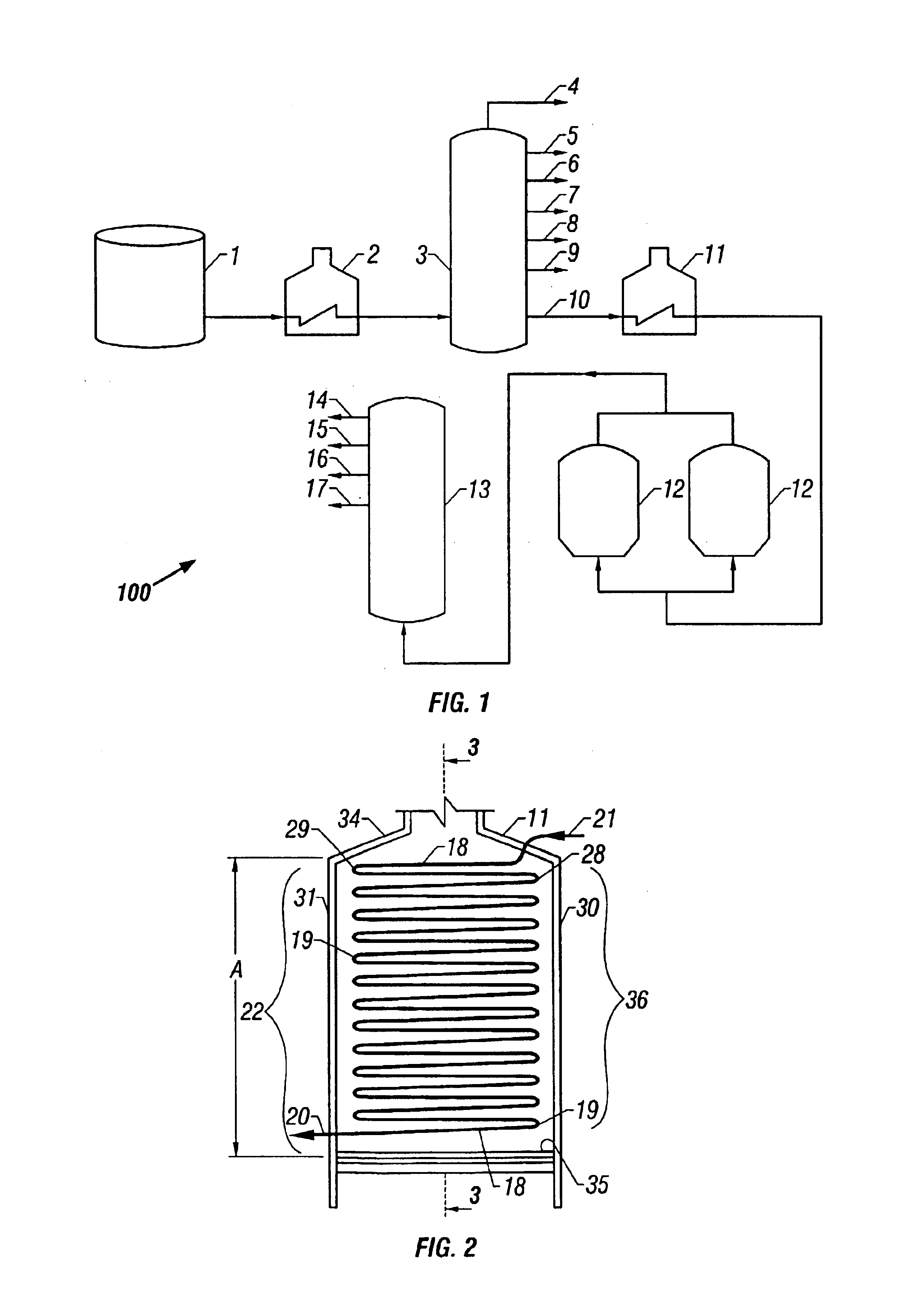
Alternate coke furnace tube arrangement

a coke furnace and tube arrangement technology, which is applied in the direction of furnaces, lighting and heating apparatus, muffle furnaces, etc., can solve the problems of increasing the residence time, and affecting the heating effect of coke heaters, so as to reduce the tendency for coke to be deposited in the tubes of the coke heater

Inactive Publication Date: 2005-02-08
BECHTEL HYDROCARBON TECH SOLUTIONS INC
View PDF16 Cites 13 Cited by
  • Summary
  • Abstract
  • Description
  • Claims
  • Application Information

AI Technical Summary

Benefits of technology

Accordingly, it is an object of the present invention to provide an improved delayed coking process in which the tendency for coke to be deposited in the tubes of the coke heater is greatly reduced.
It is another object of the present invention to provide a more efficient coke heater for a delayed coking process. A related object of the invention is to provide a coke heater that allows for a reduced residence time of the coking feedstock in the heater.
Still another object of the invention is to provide a coke heater that can be operated for extended periods of time without having to be taken off-line for coke removal.
Another object of the invention is to provide a coke heater that can provide the desired level of heating with a coke furnace of less overall height.

Problems solved by technology

Although much effort has been devoted in the past to providing conditions that will allow for the delayed coking feedstock to be heated to the cracking temperature without the formation of undesirable carbon deposits in the conduits or tubes of the coker heater, carbon deposition in the conduits of the coker heater still continues to be a problem.
As coke deposits in the conduit of the tube heater, the flow of feedstock through the heater is restricted.
The restriction of flow can lead to increased residence time that in turn can lead to the deposition of additional coke.
In addition, the coke deposits cause the tubes to become much hotter.
All these factors obviously tend to encourage the formation of still more coke within the tube of the tube heater further exacerbating the problem.
If the temperature of the tube increases enough, a tube rupture can occur.
The combination of exposing the tubes to higher temperatures and higher pressures greatly increases the probability of tube rupture and total shut down of the delayed coking process.

Method used


Image

  • Alternate coke furnace tube arrangement
  • Alternate coke furnace tube arrangement
  • Alternate coke furnace tube arrangement

Examples


Embodiment Construction

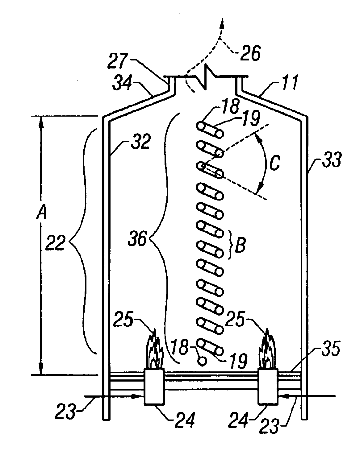
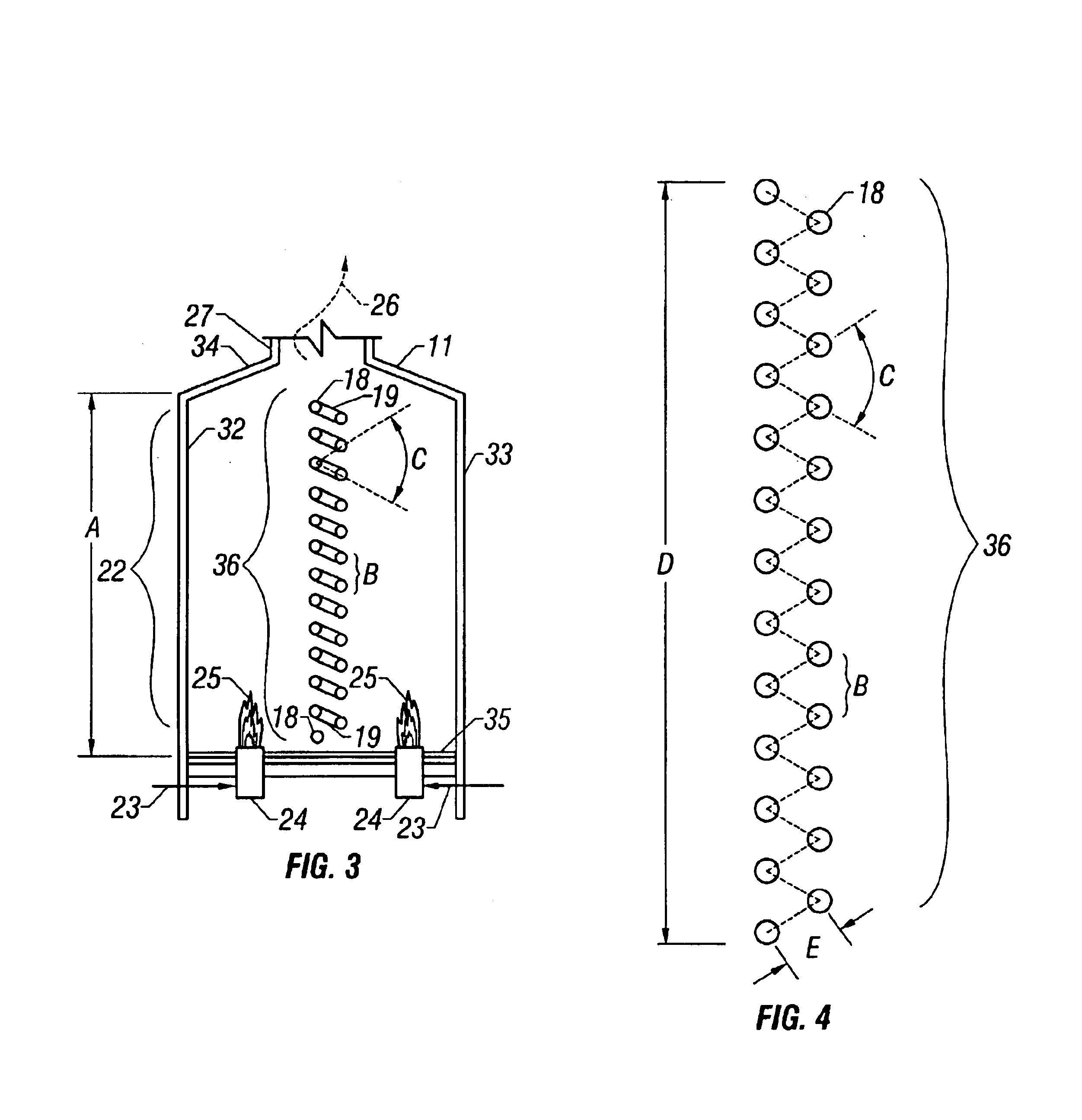
It has been discovered that by staggering the tubes in a coking furnace, particularly a double-fired coker heater, that a number of advantages may be obtained. Coking furnaces or coker heaters are peculiar in refining operations. Factors such as heat flux patterns, coke deposition, vaporization of the cracked liquid fluid as it passes through the tubes, and retention time in the heater coil tubes above critical coking temperatures all have tremendous impact on the success of operations.

It will be appreciated that the invention is not limited to the arrangement of tubes in a coking furnace but could be applied to and used in any cracking heater. Cracking heaters may include, but are not necessarily limited to, coking furnaces, thermal crackers, ethylene crackers, visbreakers, and the like. Although the invention will be described herein with particular reference to coking furnaces, it will be understood that this is only for the purpose of illustrating the invention with respect to a...


PUM


Abstract

Tubes within a radiant heating section of a coking furnace are arranged differently than in a single vertical column and connected together in a simple, planar serpentine pattern. The tubes are arranged in a plurality of offset or staggered vertical columns. This arrangement permits the upper tubes to be close to the radiant heat source and allows the tube bends connecting adjacent tubes to be of greater radius, so that the pressure at which the feedstock is passed through the tube bundle can be lower allowing more vaporization of the cracked process fluids.

Description

FIELD OF THE INVENTIONThe present invention relates to apparatus and processes for heating feedstocks in cracking heaters, and more particularly relates, in one embodiment, to apparatus for heating feedstocks in delayed coking processes by radiant heating. In a more particular aspect the present invention relates, in another embodiment, to a heater for use in heating the coking feedstock that is introduced into the coking drum in a delayed coking process and a novel coke furnace tube configuration.BACKGROUND OF THE INVENTIONIt is well known that coking is a severe thermal cracking process in which one of the end products comprises carbon, i.e. coke. The delayed coking process was initially developed to minimize refinery yields of residual fuel oil by severe cracking of feedstocks such as vacuum residuals and thermal tars to produce coke and lower molecular weight hydrocarbons. U.S. Pat. Nos. 4,049,538 and 4,547,284, the disclosures of which are incorporated herein by reference, show...

Claims


Application Information

Patent Timeline
IPC IPC(8): C10G9/00C10G9/20C10B55/00
CPCC10G9/20C10B55/00
Inventor DOERKSEN, BRIAN JAY
Owner BECHTEL HYDROCARBON TECH SOLUTIONS INC
Learn More