Probe carrier, probe fixing carrier and method of manufacturing the same

a technology of probe fixing and probe, which is applied in the direction of photomechanical treatment, optical light guides, and sequence/parallax process reactions, etc., can solve the problems of dnas that are defective in terms of the designed base sequence, the ratio of dnas that are not negligible, and the cost and time required for preparing such a probe array rise. , to achieve the effect of accurately and quickly locating a target substan

Inactive Publication Date: 2005-02-08
CANON KK
View PDF18 Cites 24 Cited by
  • Summary
  • Abstract
  • Description
  • Claims
  • Application Information

AI Technical Summary

Benefits of technology

In view of the above identified recent technological problems, it is therefore an object of the present invention to provide a probe fixing carrier that allows the operation of aligning the ejection head and the carrier to be conducte

Problems solved by technology

One of the problems to be solved for probe arrays formed by a group of a plurality of probe species is how to mount as many probes of different species, DNA probes having different base sequences for example, as possible on a single carrier.
Differently stated, it is a problem of how to mount probes in array as densely as possible.
Then, the cost and the time required for preparing such a probe array rise as the DNA chain length increases.
Furthermore, since the efficiency of nucleotide synthesis is not 100%, the ratio of DNAs that are defective in terms of the designed base sequence is not negligible.
Additionally, when photodecomposable protective groups are used for the synthesis process, the efficiency of synthesis is rather poor if compared with the use of ordinary acid-decomposable protective groups.
Besides, with the above identified known technique, since the products formed synthetically and directly on a carrier have to be used without any modification, it is not possible to sort out the DNAs having a defective base sequence from the DNAs having the designed respective base sequences and eliminate the former for the purpose of refining.
There is also a problem that it is not possible to confirm the base sequences of the DNAs synthetically formed on the carrier and ultimately obtained as an array.
This means that, if a base has not been subjected to predetermined elongation in a given elongation step probably because of an error or another in the step and hence the obtained probe array is not good, any screening operation using such a defective probe array gives rise to false results but there is no way of preventing such a problem from taking place.
In short, absence of confirmation of base sequences is the largest and most intrinsic problem of the above identified known technique.
While no problem may arise when each probe is applied with a dedicated capillary-shaped dispensing device, a mutual contamination problem will occur if a small number of capillary-shaped dispensing devices are used repeatedly for the operation, so that the capillary-shaped dispensing devices have to be cleaned sufficiently each time a new probe species is brought in to avoid such a mutual contamination problem.
Therefore, this technique is not suited for preparing a probe array comprising a wide variety of probes that are arranged densely.
Still additionally, the operation of applying a probe solution to the carrier is conducted by tapping the capillary tip to the carrier and hence not satisfactory in terms of both reproducibility and reliability.
However, this technique is basically an application of a stepwise elongation reaction on a carrier and hence is not free from certain problems including that of being unable to confirm the base sequences of the DNAs synthetically formed on the carrier as pointed out earlier to be the largest problem or the technique according to U. S. Pat. No. 5,424,186.
While the problem of conducting a cumbersome photolithography operation, using a dedicated mask in each elongation step, is dissolved with this technique, this technique is still accompanied to a certain extent by problems in terms of fixing predefined probes at respective positions

Method used


Image

  • Probe carrier, probe fixing carrier and method of manufacturing the same
  • Probe carrier, probe fixing carrier and method of manufacturing the same
  • Probe carrier, probe fixing carrier and method of manufacturing the same

Examples


example 1

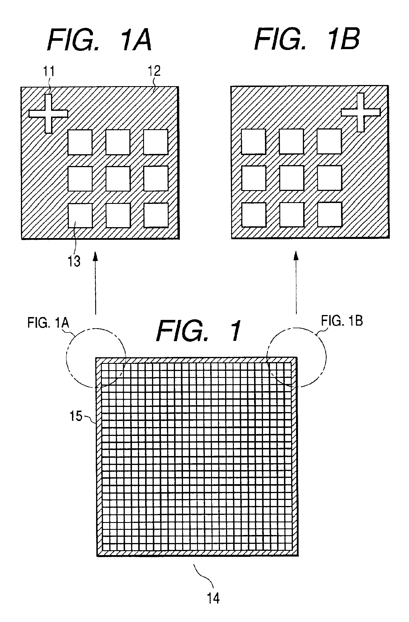
Black resist containing carbon black (“CK-A143B”: tradename, available from FUJIFILM Arch Co., Ltd.) was applied onto a glass substrate (“1737”: tradename, available from Corning), exposed to light by means of a UV aligner in a predetermined manner, developed by means of an aqueous solution of inorganic alkali and subjected to a post bake treatment in which it was heated in a clean oven at 220° C. for 60 minutes to prepare a black matrix pattern (division wall) having a film thickness of 2 μm and rectangular openings of 100 μm×200 μm. Along with the black matrix pattern, two cross-shaped indexes having a transversal part that was 30 μm wide and 150 μm long and a vertical part that was also 30 μm wide and 150 μm long were formed at two corners of a peripheral part of the chip (see FIG. 1).

Subsequently, fluorescent coloring matter rhodamine B was dissolved into a solvent to be used for ejecting the coloring matter by a liquid ejection head that contains glycerol by 7.5 wt %, urea by 7...

example 2

Evaluation of Color Mixture By Hybridization

A glass substrate was cleansed as in Example 1. Subsequently, an aqueous solution containing an aminosilane coupling agent (KBM-603: tradename, compound I, available from Shinetsu Chemical Co., Ltd.) expressed by chemical formula (I) of

(CH3O )3SiC3H6NHC2H4NH2   (I)

that had been refined by distillation under reduced pressure to a concentration of 1% was stirred at room temperature for an hour to hydrolyze the part of the methoxy group. Then, the substrate was dipped into the aqueous solution of the silane coupling agent immediately after the cleansing at room temperature for an hour. Subsequently, the substrate was washed with flowing water (ultrapure water) and dried by blowing nitrogen gas. Then, it was heated to fix the coupling agent at 120° C. in an oven.

After cooling the substrate, it was immersed into a 0.3% solution (ethanol: dimethylsulfoxide=1:1) of N-(6-maleimidecaproxy)succinimide (EMCS: compound II)

for two hours to cause EMCS ...

example 3

[Formation of Black Matrix]

Black resist (CK-A143B Resist: tradename, available from FUJIFILM Arch Co., Ltd.) containing carbon black was applied onto a glass substrate (1737: tradename, available from Corning) and subjected to a predetermined exposure session using a UV aligner and a developing operation using an inorganic aqueous alkali solution. Then, the substrate was heated in a clean oven at 220° C. for 60 minutes and subjected to a post bake treatment to prepare a black matrix pattern (division wall) having a film thickness of 2 μm and rectangular openings of 100 μm×200 μm. The length a of the division wall was made equal to 20 μm.

[Evaluation of Surface Coarseness]

The surface coarseness of the glass substrate used for forming the black matrix was observed at arbitrarily selected areas by using NanoScope IIIa AFM Dimension 3000 Stage System (tradename, available from Digital Instrument) before forming the black matrix. As a result, the substrate showed an average surface coarse...


PUM

PropertyMeasurementUnit
Fractionaaaaaaaaaa
Temperatureaaaaaaaaaa

Abstract

A carrier having indexes in a probe non-fixing region is used and solutions containing probes are applied to respective specific positions on the carrier by referring to said indexes and fixed. The position of a target compound that is specifically bonded to a probe fixed to a probe carrier manufactured by a method according to the invention can be accurately and quickly detected by referring to the indexes.

Description

BACKGROUND OF THE INVENTION1. Field of the InventionThis invention relates to a method of manufacturing a probe carrier by applying a probe solution to a specific position on a carrier, utilizing one or more than one indexes and an ink-jet method in particular. It also relates to a probe carrier manufactured by such a manufacturing method and a method of identifying the position of the target substance bonded to the probe on such a probe carrier by utilizing such indexes.2. Related Background ArtWhen analyzing the base sequence of a gene DNA or conducting a gene diagnosis for a number of items simultaneously, probes of different types are needed to single out a DNA having a target base sequence in order to raise the reliability of operation. DNA microchips have been attracting attention as means for providing probes of a number of different types to be used for such sorting operations. A large number of solution specimens (e.g., 96, 384 or 1,536 specimens) containing proteins or dru...

Claims


Application Information

Patent Timeline
IPC IPC(8): B01L3/00B01J19/00B05D3/00C12M1/34C12Q1/68C40B40/06C40B40/10C40B40/12C40B60/14
CPCB01J19/0046C40B60/14B01J2219/00378B01J2219/00432B01J2219/00497B01J2219/0056B01J2219/00576B01J2219/00585B01J2219/00596B01J2219/00605B01J2219/00612B01J2219/00626B01J2219/00635B01J2219/00659B01J2219/00677B01J2219/00707B01J2219/00722B01J2219/00725B01J2219/00729B01J2219/00731B01L3/5085C40B40/06C40B40/10C40B40/12B01J2219/00317
Inventor OKAMURA, NOBUYUKIOKAMOTO, TADASHIKAMEYAMA, MAKOTO
Owner CANON KK
Why Eureka
Try Eureka