Power supply with control circuit for controlling a high voltage circuit using a low voltage circuit

a power supply and control circuit technology, applied in the field of power supply circuits, can solve the problems of limiting the use of transformers in certain areas, the low voltage section of the system the low voltage section cannot be used to provide the gate voltage directly, etc., to achieve the effect of small and less expensive implementation, high degree of portability, and fast respons

Inactive Publication Date: 2005-02-08
BANK OF AMERICA N A
View PDF13 Cites 29 Cited by
  • Summary
  • Abstract
  • Description
  • Claims
  • Application Information

AI Technical Summary

Benefits of technology

The invention provides a power supply with integral control circuit for providing a low-voltage control signal with capacitive coupling to a high-voltage section having an output for powering a load. The power supply is adapted to operate the high-voltage section in response to a signal firm the low-voltage section.
According to one aspect of the invention, the integral control circuit and capacitive coupling are implemented as a single IC.
According to another aspect of the invention, the integral control circuit is implemented as a full bridge rectifier driver circuit.
Embodiments of the invention disclosed include implantable cardiac defibrillator circuits where a bridge section capacitively couples the low-voltage section to the high-voltage sec...

Problems solved by technology

The low voltage section of the system cannot, therefore, be used to provide the gate voltage directly.
Although transformers combined with diode rectifiers may be adequate for shifting voltage levels, design considerations limit their use in certain situations.
First, transformers are bulky, and hence, are unsuitable in certain applications where minimizing the three-dimensional...

Method used


Image

  • Power supply with control circuit for controlling a high voltage circuit using a low voltage circuit
  • Power supply with control circuit for controlling a high voltage circuit using a low voltage circuit
  • Power supply with control circuit for controlling a high voltage circuit using a low voltage circuit

Examples


Embodiment Construction

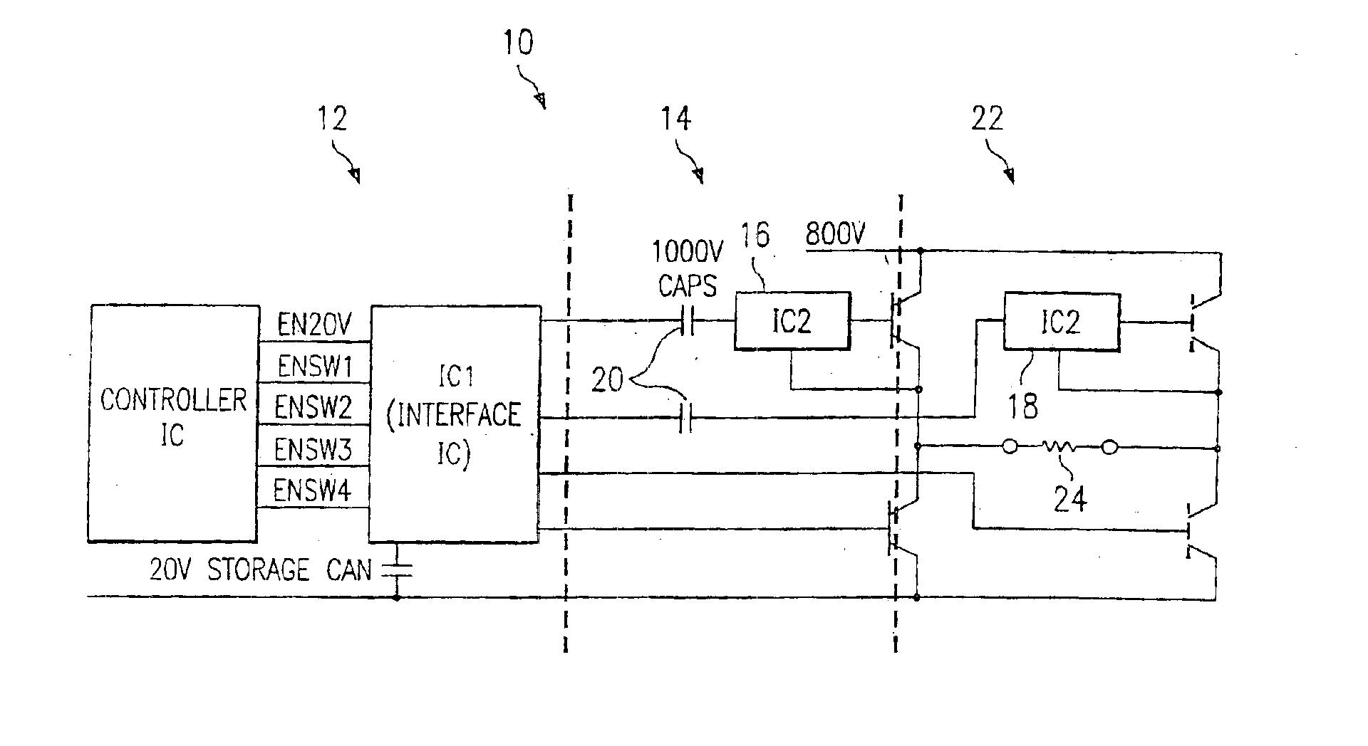
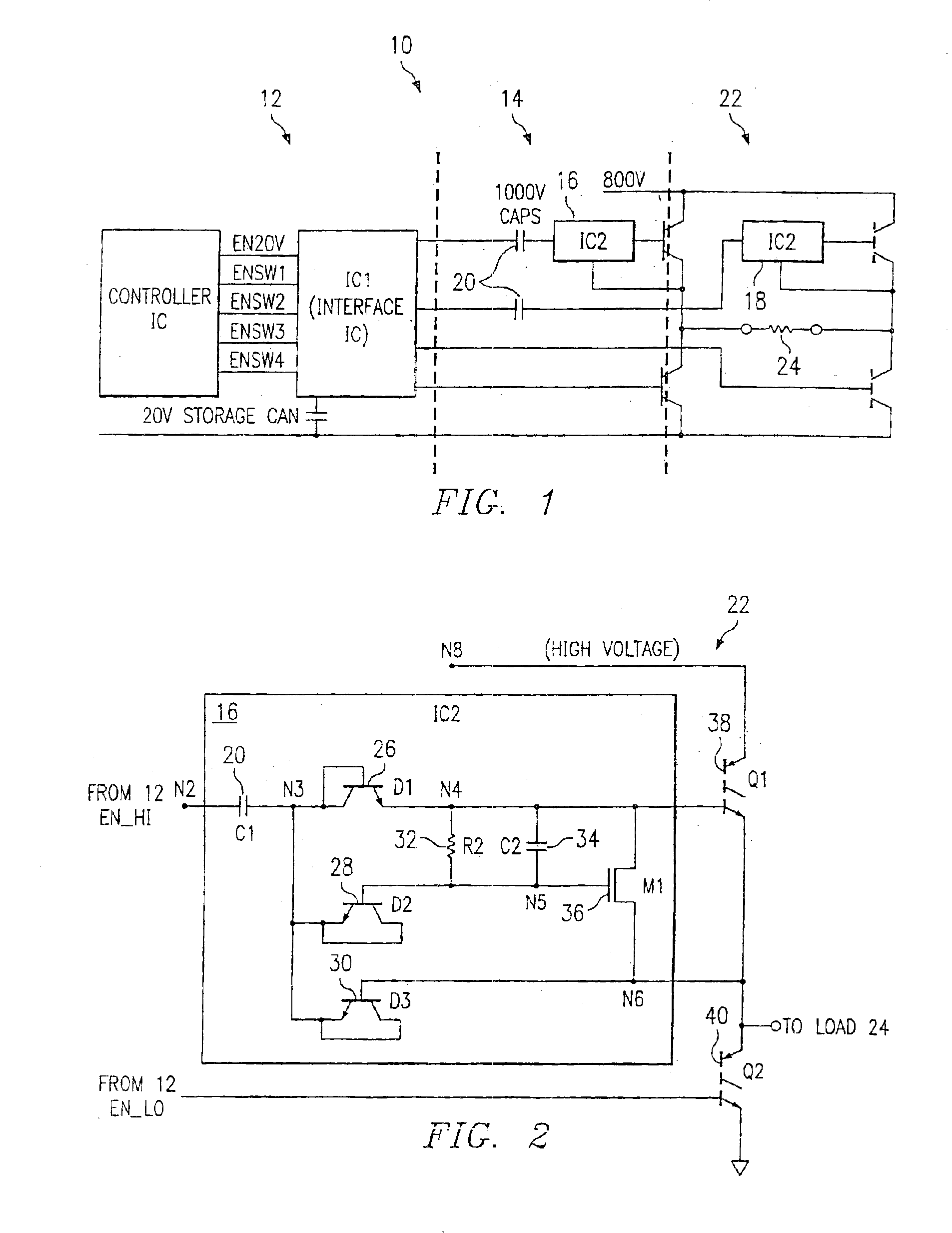
In FIG. 1 is shown a block diagram of an example of the invention in the form of a full image driver circuit 10. A low voltage section 12 provides a relatively low voltage control signal to a bridge section 14. Preferably, the control signal is an oscillating signal within a frequency range (FOSC) of about 1 MHz-10 MHz, at about 6V-24V, although other generating frequencies may be employed. As shown in FIG. 1, the bridge section 14 may have a high portion 16 and a low portion 18, which are functionally and physically mirror-images of one another, providing a full bridge driver circuit 10. The bridge section 14 may be contained on a single IC. Isolation capacitors 20 are used to couple the low voltage section 12 with the bridge portion 14. The isolation capacitors 20 are preferably included on an IC with the bridge portion 14, although they may be alternatively external, or included on an IC with the low voltage section 12. The isolation capacitors 20 are selected to withstand the ma...


PUM


Abstract

Disclosed is a power supply with a control circuit comprising a capacitively coupled bridge circuit (10) for using a low-voltage circuit to operate a high-voltage circuit. The invention maintains isolation between the high-and low voltage sections by using a capacitor (20).

Description

TECHNICAL FIELDThis invention relates to a power supply circuit, and more specifically, to a capacitively coupled bridge circuit for using a low-voltage circuit section to control a high-voltage circuit section while maintaining isolation between the high- and low-voltage sections.BACKGROUND OF THE INVENTIONIn many electronic systems a low voltage source is often needed to control a corresponding high voltage source. One such need, for example, is commonly found in a device known as an Implantable Cardiac Defibrillator (ICD), in which a high voltage pulse is controlled by a low voltage integrated circuit (° C.). In many instances, delivery of the higher voltage is accomplished by way of a non-complementary high voltage switching matrix encompassing a bridge configuration. This switching element frequently employs N-channel Metal-Oxide Semiconductor Field Effect Transistors (MOSFETs), or Insulated Gate Bipolar Transistors (IGBTs), or Silicon Controlled Rectifiers (SCR) depending on t...

Claims


Application Information

Patent Timeline
IPC IPC(8): A61N1/39H01L21/70H01L21/761H01L27/085H01L27/088
CPCH01L27/088H01L21/761A61N1/3956A61N1/3912
Inventor COMEAU, ALAIN R.WEILAND, JONAS PER LUDVIG
Owner BANK OF AMERICA N A
Why Eureka
Try Eureka