Photonic-crystal fibers and photonic-crystal fiber devices

a technology of photonic crystal fibers and fibers, applied in the field of photonic crystal fibers and photonic crystal fibre devices, can solve the problems of loss, too strong at longer wavelengths, and too weak at shorter wavelengths

Inactive Publication Date: 2005-02-08
CRYSTAL FIBRE AS
View PDF16 Cites 30 Cited by
  • Summary
  • Abstract
  • Description
  • Claims
  • Application Information

AI Technical Summary

Benefits of technology

wherein the evanescent wave is less closely confined to the vicinity of the core by decreasi

Problems solved by technology

Thus, if the strength of interaction in an evanescent-wave device is optimal at one wavelength, it

Method used


Image

  • Photonic-crystal fibers and photonic-crystal fiber devices
  • Photonic-crystal fibers and photonic-crystal fiber devices
  • Photonic-crystal fibers and photonic-crystal fiber devices

Examples


Embodiment Construction

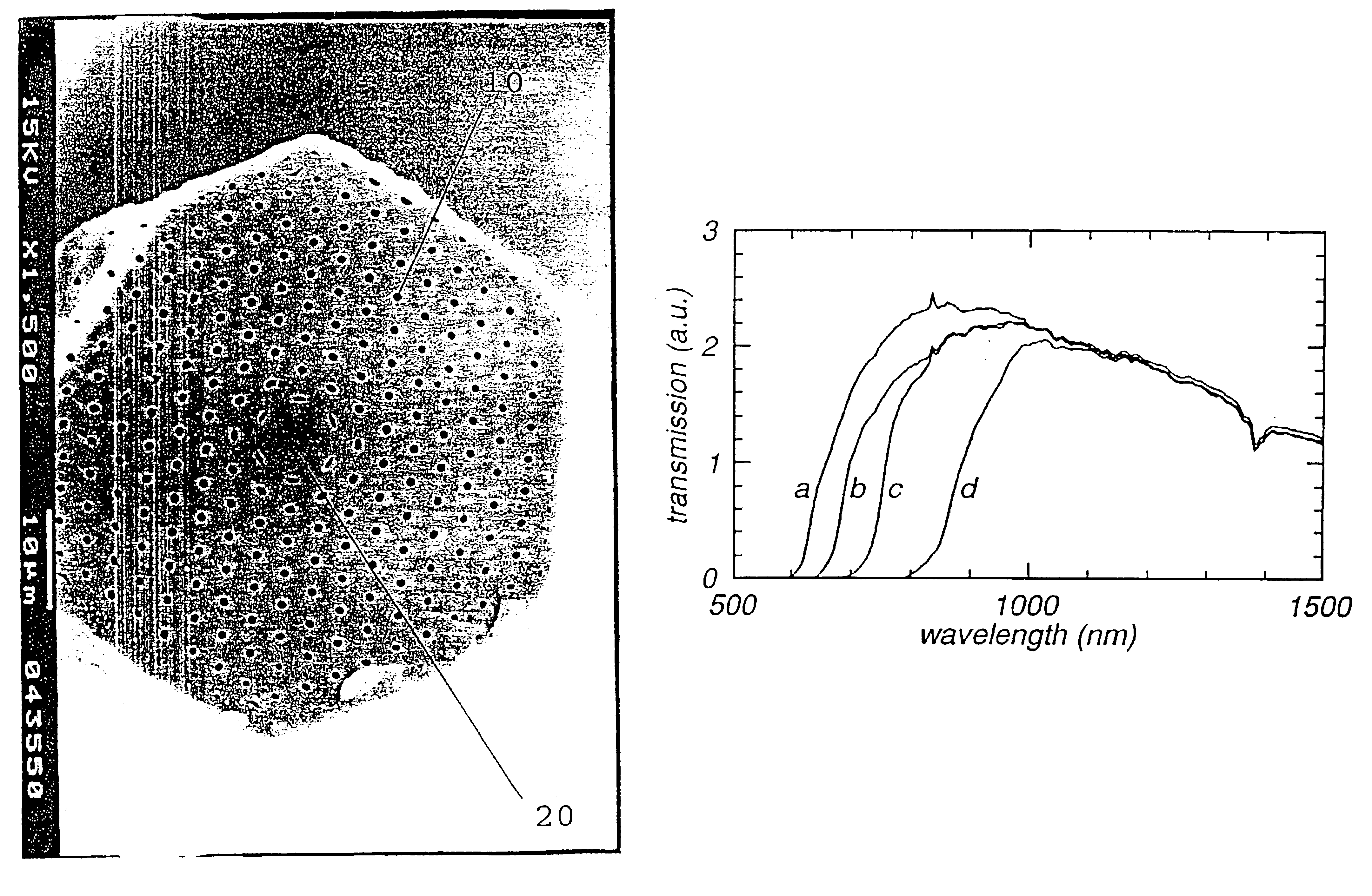
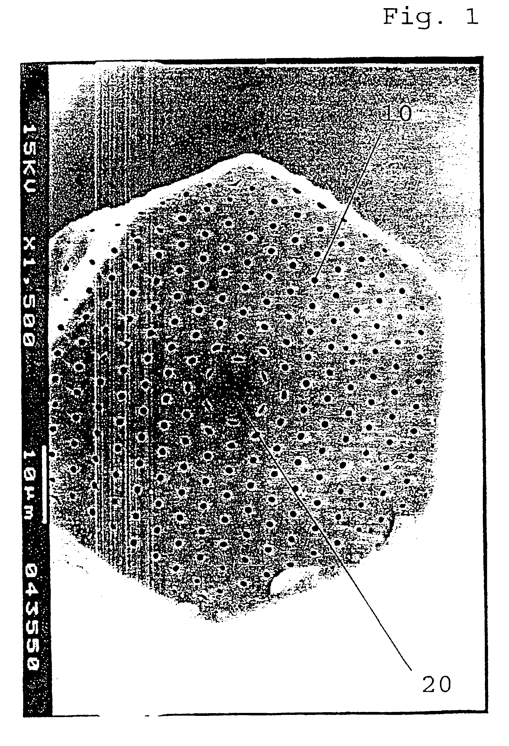
The fibre of FIG. 1 is about 65 μm across, of hexagonal cross-section and includes a cladding region of undoped silica containing a lattice of holes 10. The holes 10 are arranged at the centres of hexagonal unit cells. (Some of the holes have been distorted by the fabrication process). The diameter of the holes 10 is 0.7 μm and the pitch 3.5 μm. The fibre also includes a central unit cell 20 that is a ‘defect’: it has no hole at its centre and it is made from silica doped with fluorine.

In the manufacture of the fibre, silica capillaries were stacked in a close-packed array to form a fibre preform. At the centre of the array, a solid rod of fluorine-doped silica was used, instead of a silica capillary, to form the core, with an index depression of 1.2×10⁻³. The preform was then drawn, using a drawing tower, into a fibre.

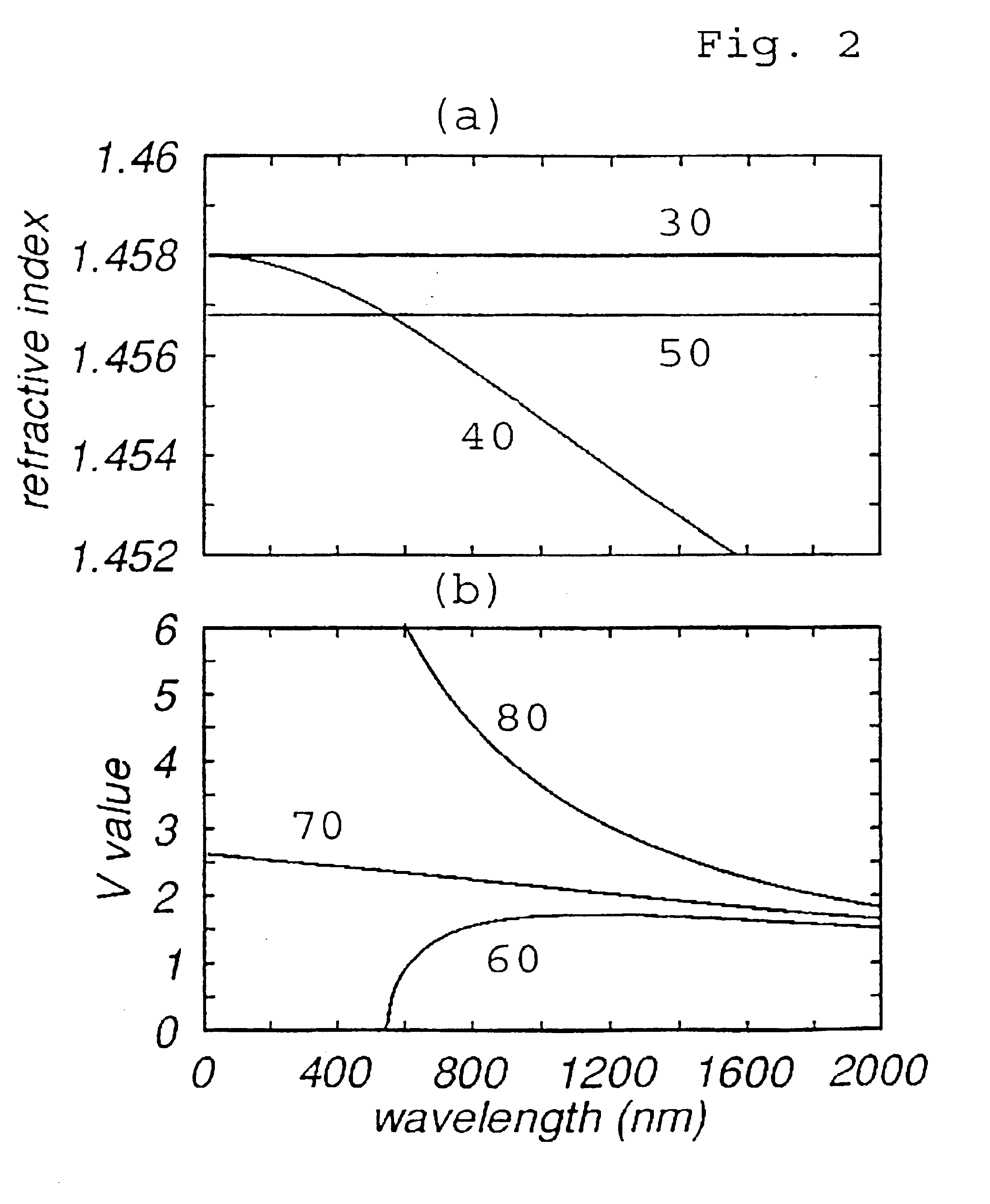
FIG. 2(a) shows that the refractive index of pure silica (plot 30) is higher than that of fluorine doped silica (plot 50) (note: material dispersion has been neglecte...


PUM

PropertyMeasurementUnit
Structureaaaaaaaaaa
Abrasiveaaaaaaaaaa
Metallic bondaaaaaaaaaa

Abstract

A photonic crystal fiber comprising: a core (20) having a refractive index; and a cladding region (10) at least substantially surrounding the core (20) and comprising a bulk material having a second refractive index that is higher that the first refractive index, the bulk material containing an arrangement of elongate, longitudinal holes that comprise hole material of a third refractive index that is lower than the first refractive index; such that an electromagnetic mode guided in the core (20) has an evanescent wave that becomes more closely confined to the vicinity of the core (20) as the wavelength of the electromagnetic mode is increased over a first range of wavelengths.

Description

BACKGROUND OF THE INVENTION1. Field of the InventionThis invention relates to the field of photonic-crystal fibres and photonic-crystal fibre devices.2. Description of the Related ArtSingle-mode optical fibres are widely used in diverse applications in fields including telecommunications and sensing. A typical optical fibre of the prior art (referred to hereunder as a “standard fibre”) is made entirely from solid transparent materials, such as glass. The transparent material in one part (usually the middle) of a cross-section through the fibre has a higher refractive index than transparent material in the rest of the cross-section (the “cladding”) and forms an optical “core” within which light is guided by total internal reflection.Although light guided by total internal reflection in a fibre propagates predominantly in the high-index core, some light extends into the surrounding, lower-index cladding. That light is called the “evanescent wave”; its intensity decreases quasi-exponen...

Claims


Application Information

Patent Timeline
IPC IPC(8): C03B37/012G02B6/122G02B6/02
CPCB82Y20/00C03B37/01205G02B6/1225G02B6/02323G02B6/02347C03B2203/14G02B6/02371C03B2203/42
Inventor RUSSELL, PHILLIP ST. JOHNBIRKS, TIMOTHY ADAMKNIGHT, JONATHAN CAVEMANGAN, BRIAN JOSEPH
Owner CRYSTAL FIBRE AS
Why Eureka
Try Eureka