Article and process for cleaning optical surfaces

a technology of optical surfaces and cleaning methods, applied in the direction of carpet cleaners, instruments, photosensitive materials, etc., can solve the problems of optical fiber alignment, attenuation of light signals passing through the connection zone between optical fibers, and attenuation of optical fibers passing through the connection zone, etc., to achieve convenient surface cleaning, simple cleaning system, and sufficient conductivity

Inactive Publication Date: 2005-02-15
3M INNOVATIVE PROPERTIES CO
View PDF15 Cites 33 Cited by
  • Summary
  • Abstract
  • Description
  • Claims
  • Application Information

AI Technical Summary

Benefits of technology

[0009]The present invention addresses the need for a simple cleaning system for optical surfaces by providing a relatively compact cleaning tool having a cleaning head assembly at one end of a shaft of variable length. A control mechanism, separated from the cleaning head by the length of the shaft, provides a convenient means for remotely initiating cleaning action within the cleaning head assembly. Coupling between the cleaning head and the control mechanism, also referred to herein as an actuator, preferably uses a rod or cable connector. A cleaning article according to the present invention provides a tool capable of reaching t

Problems solved by technology

The use of optical fiber on backplanes presents a unique set of problems including problems of optical fiber alignment and maintaining the cleanliness of optical fiber surfaces.
One issue of alignment affects optimal positioning of daughter card fiber optic connectors and receiving connectors located on the backplane.
Misalignment of optical fiber ends may cause attenuation of light signals passing through a connection zone between optical fibers.
Optical fiber surface cleanliness becomes a problem when exposed ends of optical fibers reside in relatively inaccessible locations within the backplane.
The presence of obscuring coatings of dirt particles at the interface between connected optical fibers impedes the passage of light.
In the case of single mode fiber products, for example, the w

Method used


Image

  • Article and process for cleaning optical surfaces
  • Article and process for cleaning optical surfaces
  • Article and process for cleaning optical surfaces

Examples


Embodiment Construction

[0051]As required, detailed embodiments of the present invention are disclosed herein; however, it is to be understood that the disclosed embodiments are merely exemplary of the invention that may be embodied in various and alternative forms. The figures are not necessarily to scale, some features may be exaggerated or minimized to show details of particular components. Therefore, specific structural and functional details disclosed herein are not to be interpreted as limiting, but merely as a basis for the claims and as a representative basis for teaching one skilled in the art to variously employ the present invention.

[0052]Furthermore, elements may be recited as being “coupled;” this terminology's use contemplates elements being connected together in such a way that there may be other components interstitially located between the specified elements, and that the elements so specified may be connected in fixed or movable relation one to the other.

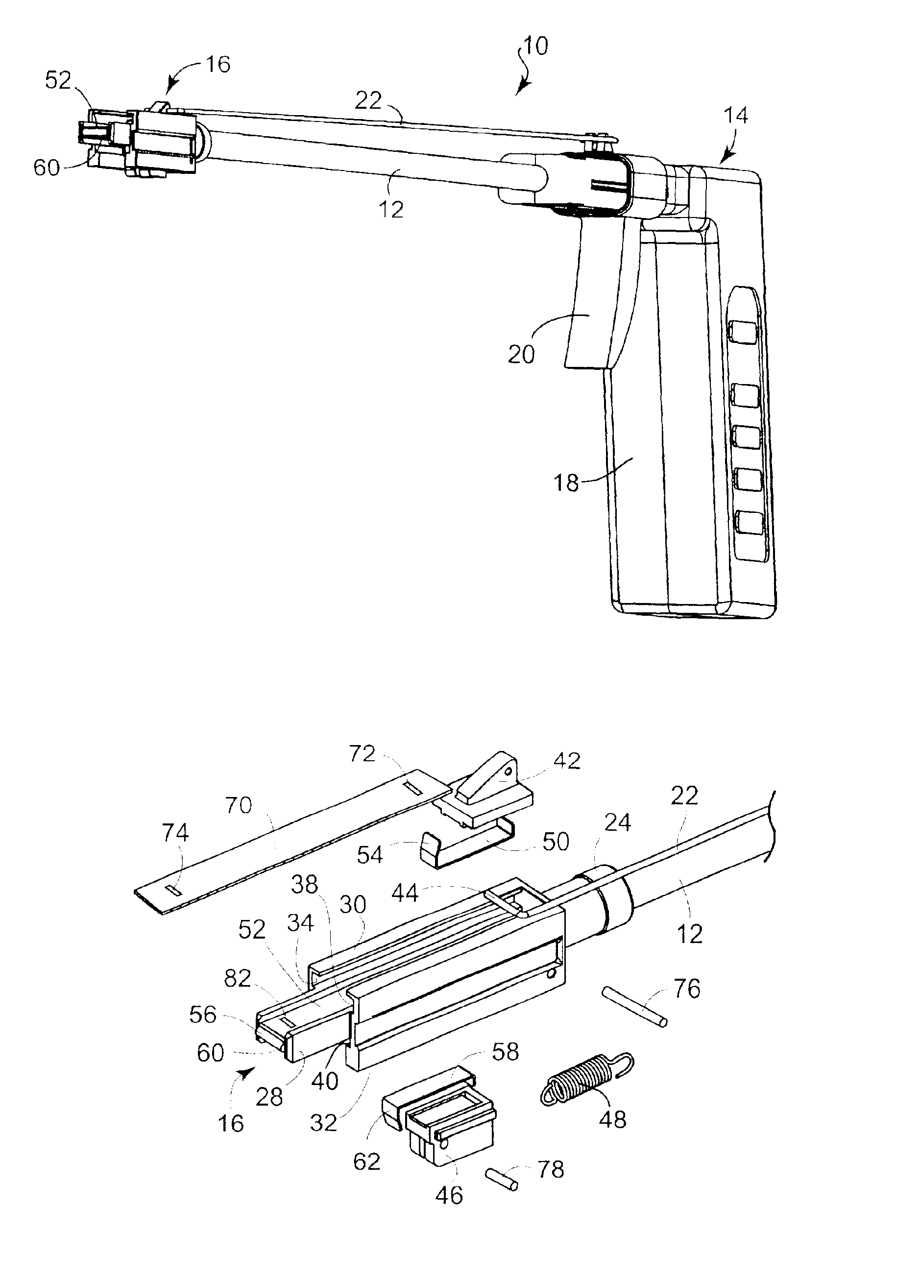
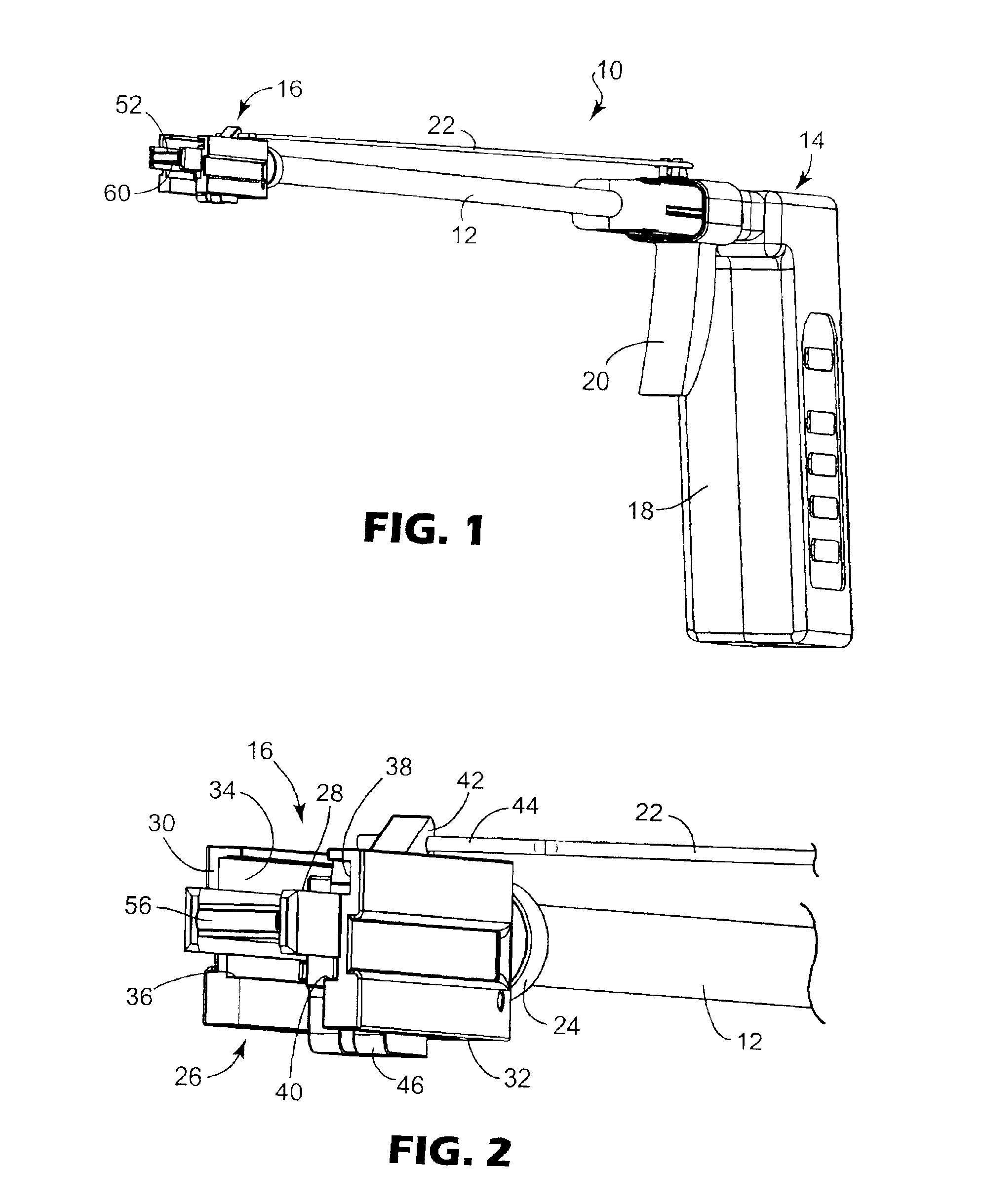
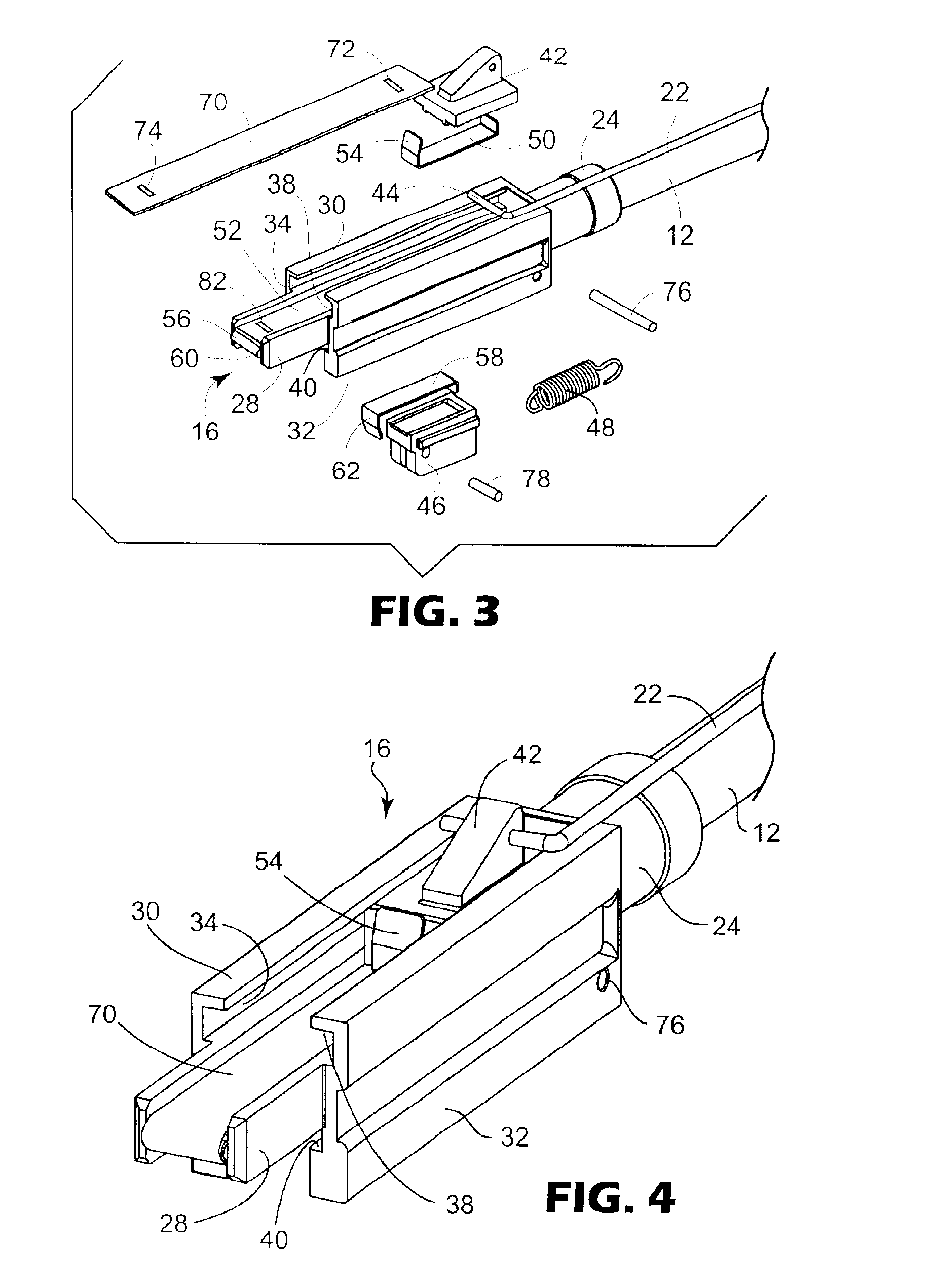
[0053]Referring now to the figures...


PUM


Abstract

An article and process for cleaning relatively inaccessible and recessed surfaces, including a shaft having a first end opposite a second end with a cleaning head assembly, including a movable strip of buffing material, at the first end of the shaft. The article has an actuator at the second end of the shaft; and a connector coupling the cleaning head assembly to the actuator to move the movable strip during positional change of the actuator. Repeated positional change of the actuator produces reciprocatory movement in the movable strip of buffing material to produce a rubbing, cleaning action of the material against a recessed surface.

Description

FIELD OF THE INVENTION[0002]The invention relates to an article and process for cleaning optical surfaces particularly optical fibers having surfaces that are inaccessible without the use of special tools.BACKGROUND OF THE INVENTION[0003]Considering the rapid expansion of the use of cellular phones, increasing demand for access to the Internet, and business use of fiber optic links, there is convincing evidence of a continuing, increasing need to expand the capacity of telecommunications systems. As telecommunications systems expand there is also a need to upgrade essential equipment, such as telephone switching equipment, by replacing copper conductors of older installations with fiber optic signal transmission media. Fiber optics technology offers the superior bandwidth capability that is needed to handle the explosive increase in today's signal traffic.[0004]Replacement of copper conductors by optical fibers has a direct effect upon the backplanes of switching equipment. The use ...

Claims


Application Information

Patent Timeline
IPC IPC(8): B08B1/00G02B6/38
CPCB08B1/00B08B1/008G02B6/3898G02B6/3807G02B6/3866B08B2240/02
Inventor LODER, HARRY A.SHOEMAKER, CURTIS L.
Owner 3M INNOVATIVE PROPERTIES CO
Why Eureka
Try Eureka