Manufacturing system for aircraft structures and other large structures

a manufacturing system and aircraft structure technology, applied in the field of production systems, can solve the problems of large and expensive foundations, loss of productive use of machines during certification, qualification and maintenance of machines, and significant amount of time and resources required for training workers

Inactive Publication Date: 2005-02-15
THE BOEING CO
View PDF26 Cites 58 Cited by
  • Summary
  • Abstract
  • Description
  • Claims
  • Application Information

AI Technical Summary

Benefits of technology

The present invention addresses the above needs and achieves other advantages by providing a production system employing non-fixed-base machines that interface with a workpiece via an index system that can travel along with the workpiece in a CFM or pulse-flow manufacturing process, the index system accurately locating the machine relative to the workpiece by physically indexing to index devices removably mounted on the workpiece. In accordance with one aspect of the invention, a production system for manufacturing a workpiece comprises an index system including a plurality of index devices removably mounted on the workpiece at known longitudinall

Problems solved by technology

Some of the well-known drawbacks of using such machines include the high initial capital investment to acquire and install the equipment and the large and expensive foundations that they require, the significant amount of time and resources required for training workers how to operate the complex machines and for maintaining and supporting the machines, and the loss of productive use of the machines during certification, qualification, and maintenance of the machines.
Additionally, large fixed-based machines do not lend themselves to Continuous Flow Manufacturing (CFM), which is considered by most leading manufacturing experts to be the most eff

Method used


Image

  • Manufacturing system for aircraft structures and other large structures
  • Manufacturing system for aircraft structures and other large structures
  • Manufacturing system for aircraft structures and other large structures

Examples


Embodiment Construction

The present invention now will be described more fully hereinafter with reference to the accompanying drawings, in which preferred embodiments of the invention are shown. This invention may, however, be embodied in many different forms and should not be construed as limited to the embodiments set forth herein; rather, these embodiments are provided so that this disclosure will be thorough and complete, and will fully convey the scope of the invention to those skilled in the art. Like numbers refer to like elements throughout.

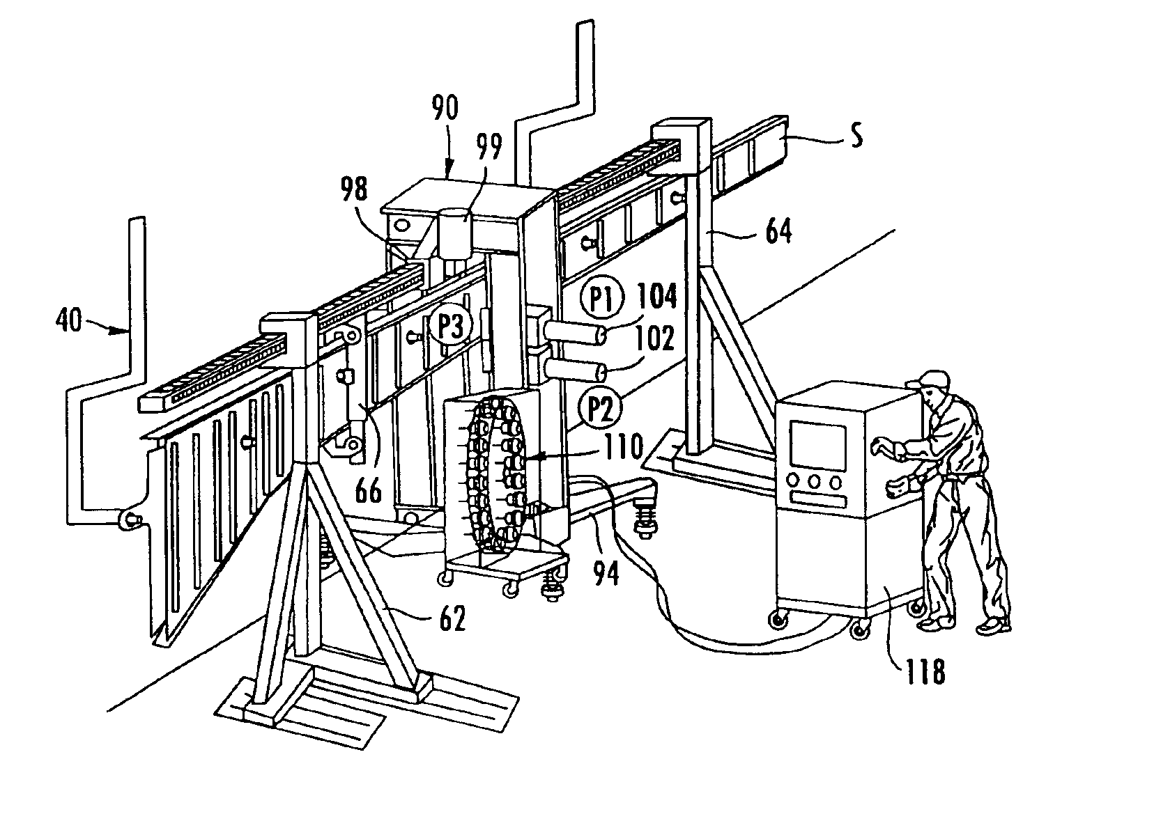
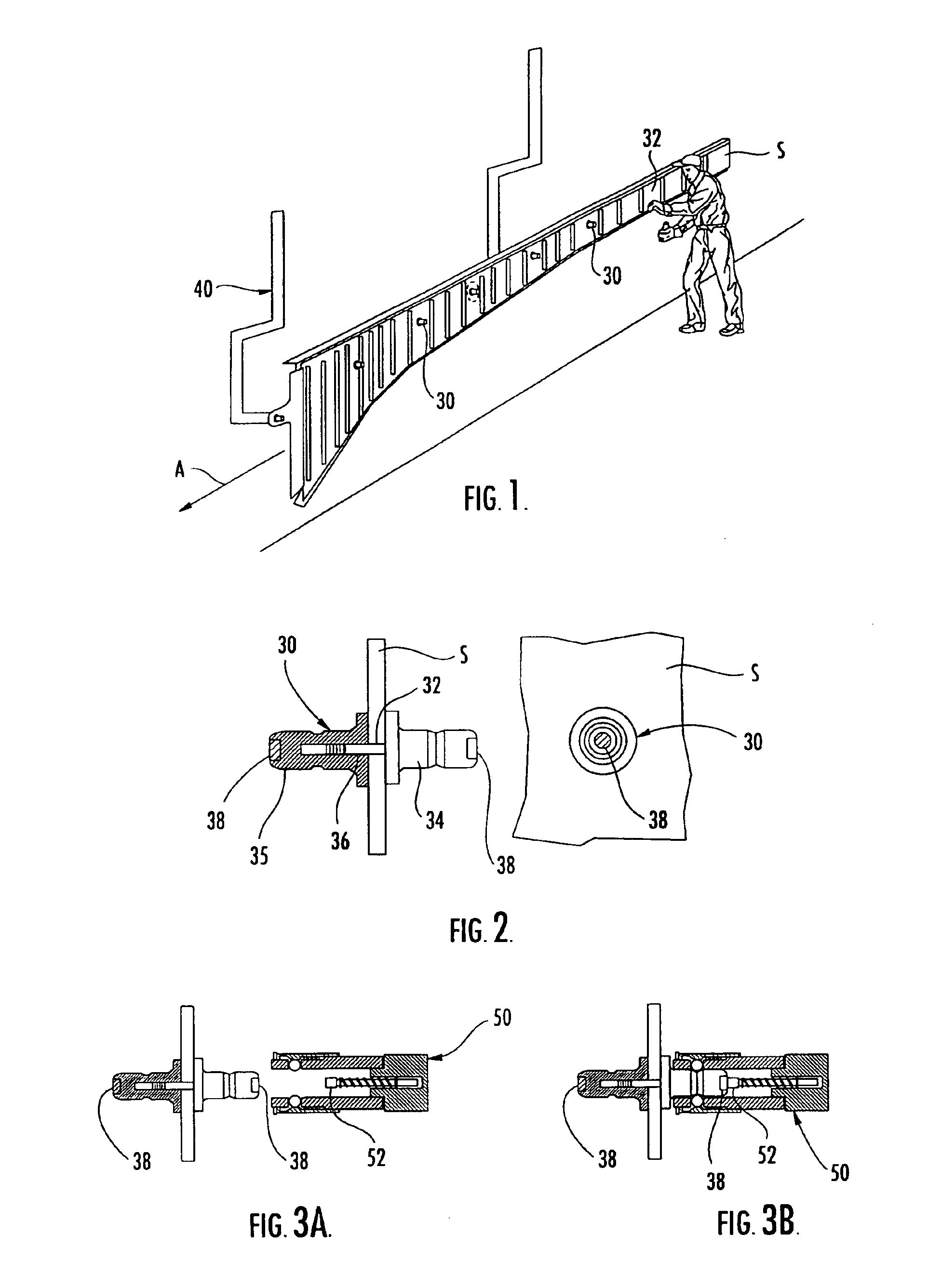
With reference to FIG. 1, a spar S is shown being fitted with index devices 30 in accordance with some embodiments of the present invention. The spar S is supported by a material handling system 40 that transports the spar along a process flow path as indicated by the arrow A. The production system can employ either a continuous-flow manufacturing process wherein the spar S continually moves along the process flow path, or a pulse-flow manufacturing process wher...


PUM

PropertyMeasurementUnit
Lengthaaaaaaaaaa
Thicknessaaaaaaaaaa
Forceaaaaaaaaaa

Abstract

A production system for manufacturing a workpiece comprises an index system including a plurality of index devices removably mounted on the workpiece at known longitudinally spaced locations therealong, and a longitudinally extending index member releasably engaged with at least two of the index devices such that a position and orientation of the index member are fixed relative to the workpiece by the index devices, the index member having position-indicating features distributed therealong. The production system further comprises a machine module mounted for longitudinal movement along the index member and operable to perform an operation, the machine module being operable to detect the position-indicating features on the index member and thereby determine a position of the machine module relative to the workpiece.

Description

FIELD OF THE INVENTIONThe present invention relates to a production system for manufacturing large structures such as aircraft spars, planks, wing sections, fuselage sections, and the like, and other large structures. The invention relates more particularly to a production system of non-fixed-base type employing either a continuous-flow or pulse-flow process and using machine modules that are brought into engagement with the workpiece as the workpiece travels along its process flow path and that index to the workpiece with the aid of index devices mounted on the workpiece.BACKGROUND OF THE INVENTIONLarge structures such as those mentioned above are traditionally manufactured using large fixed-based machines such as robotic drilling machines and riveting machines. Some of the well-known drawbacks of using such machines include the high initial capital investment to acquire and install the equipment and the large and expensive foundations that they require, the significant amount of t...

Claims


Application Information

Patent Timeline
IPC IPC(8): B23Q16/00B23Q9/00B64F5/00G01M99/00
CPCB21C51/005B21J15/142B21J15/28B23Q9/0042B23Q16/00B23Q16/001B23Q17/2233B64F5/0009B64F5/0036B21J15/14Y10T483/1729Y10T408/173Y10T29/53087Y10T483/1752Y10T29/49829Y10T29/53961Y10T409/308176Y10T408/03Y10T29/4978Y10T29/53061Y10T29/49943Y10T29/49956Y10T408/175Y10T29/5191Y10T408/57Y10T408/56245Y10T29/5118Y10T29/49778Y10T29/49895Y10T29/53978Y10T483/1748Y10T29/49948Y10T409/306384Y10T408/5612Y10T483/1736Y10T29/53052Y10T408/567Y10T29/534Y10T483/10Y10T409/307672Y10T408/21Y10T408/93B64F5/10B64F5/50
Inventor HAZLEHURST, LAURANCE N.PHILPOTT, JR., BOBBY C.BUTTRICK, JAMES N.JONES, DARRELL D.PAPANIKOLAOU, KOSTADINOS D.BANKS, DAVID P.ROWE, TERRENCE J.OUTOUS, RONALDGLAISYER, CHARLES H.TOWNSEND, HARRY E.BOBERG, MARKNELSON, PAUL ELFESPORTER, JOHN R.
Owner THE BOEING CO
Why Eureka
Try Eureka