Carbonized resin coated anode

Inactive Publication Date: 2005-02-15
THE UNITED STATES OF AMERICA AS REPRESETNED BY THE SEC OF THE AIR FORCE
View PDF17 Cites 2 Cited by
  • Summary
  • Abstract
  • Description
  • Claims
  • Application Information

AI Technical Summary

Problems solved by technology

One major drawback with these materials is the production of secondary electrons, plasmas, and neutral gasses upon electron impact.
Plasmas not only increase the pressure but also cause the tube to short electrically, limiting the duration of mic

Method used


Image

  • Carbonized resin coated anode
  • Carbonized resin coated anode
  • Carbonized resin coated anode

Examples


Embodiment Construction

Conventional vacuum tube anodes / collectors produce secondary electrons from the impact of electrons from the cathode, along with plasmas and neutral gasses that degrade the performance of the tube. The carbonized resin anode / collector coating of the present invention significantly reduces these problems. The coating can readily be applied to any anode shape or configuration.

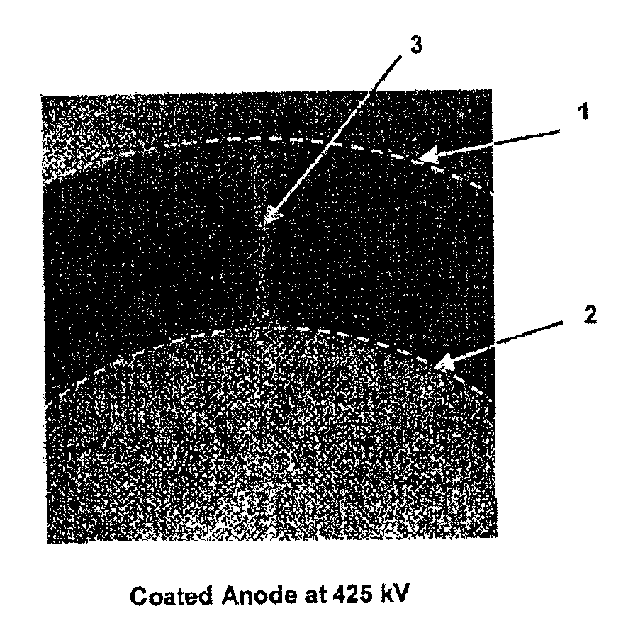
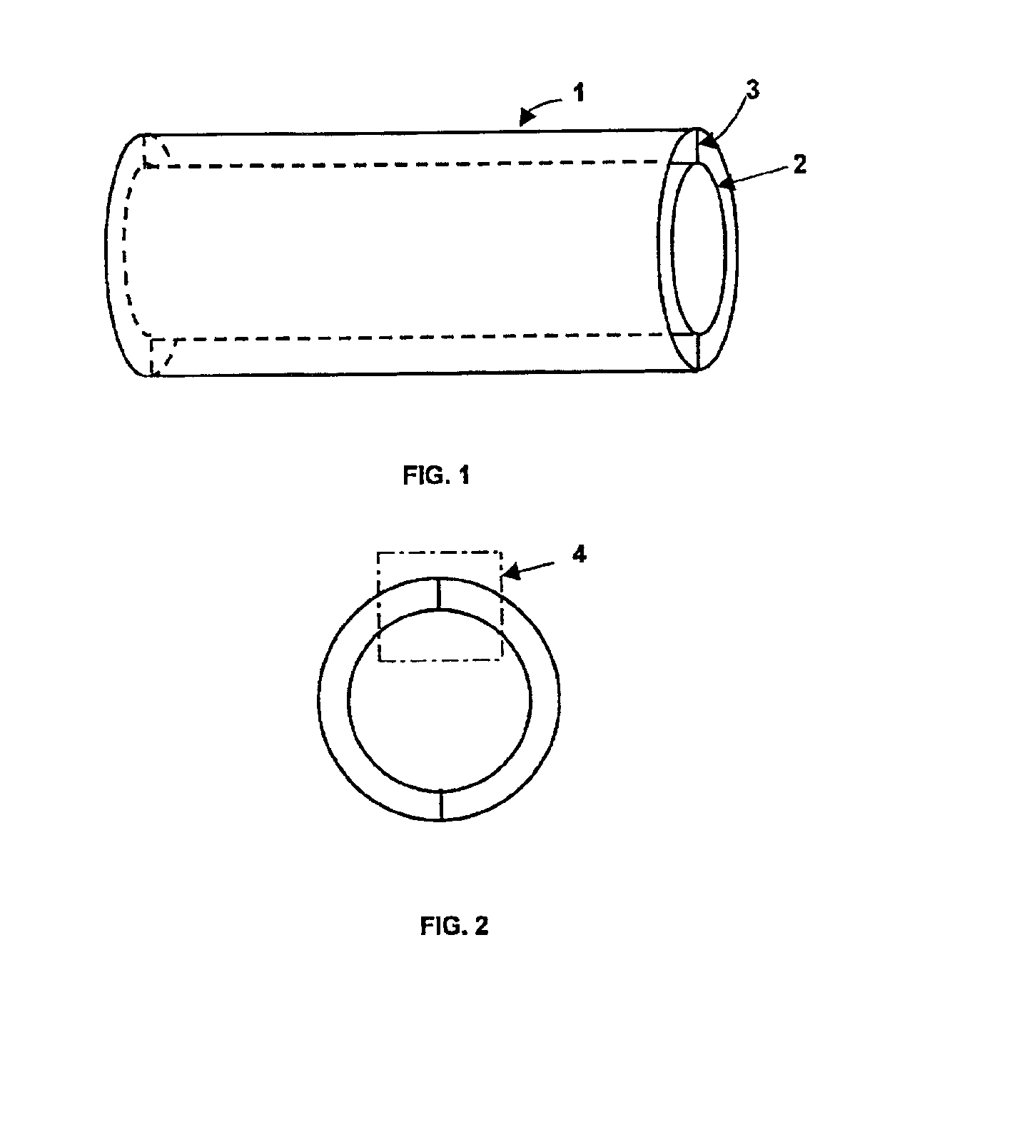
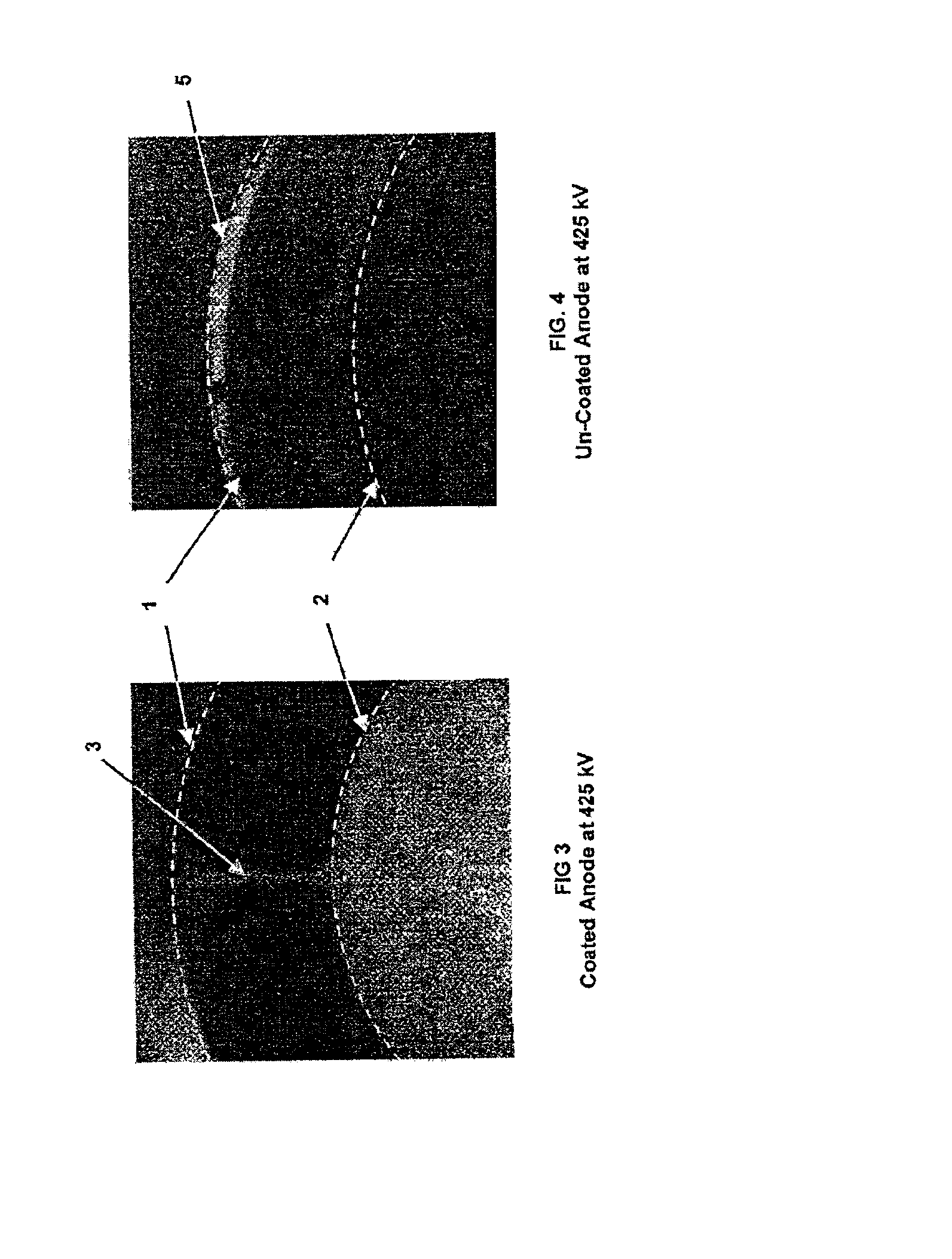
As an example, an anode structure having a cylindrical geometry is depicted in FIG. 1 with an end view shown in FIG. 2. A cathode 2 emits electrons that are accelerated to high energy towards the anode / collector 1. The cylindrical cathode is held in position within the cylindrical anode by a support 3. Electrons impact the anode at very high energy, leading to the production of neutral gas, plasma, and secondary electrons.

To reduce these deleterious effects, the anode / collector is coated using a carbon pyrolysis technique. First, a carbon surface or metal surface coated with a thin film of carbon is obtained in t...


PUM

PropertyMeasurementUnit
Temperatureaaaaaaaaaa

Abstract

A vacuum tube having its anode/collector coated with carbonized resin plus pyrocarbon material to reduce out-gassing and secondary electron emission and the method of coating the anode/collector.

Description


Claims


Application Information

Patent Timeline
Owner THE UNITED STATES OF AMERICA AS REPRESETNED BY THE SEC OF THE AIR FORCE
Why Eureka
Try Eureka