Method and apparatus for signal reception using ground termination and/or non-ground termination

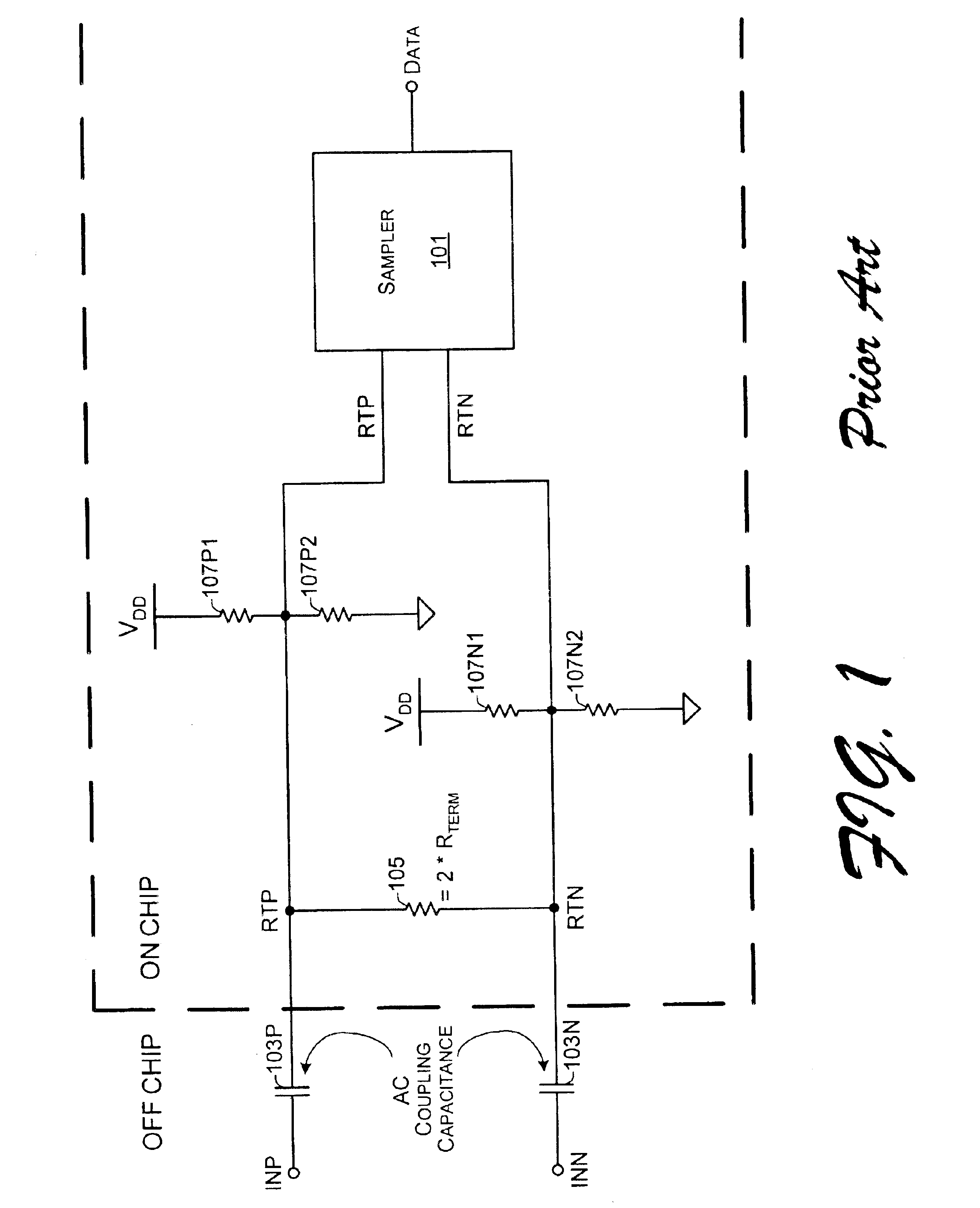
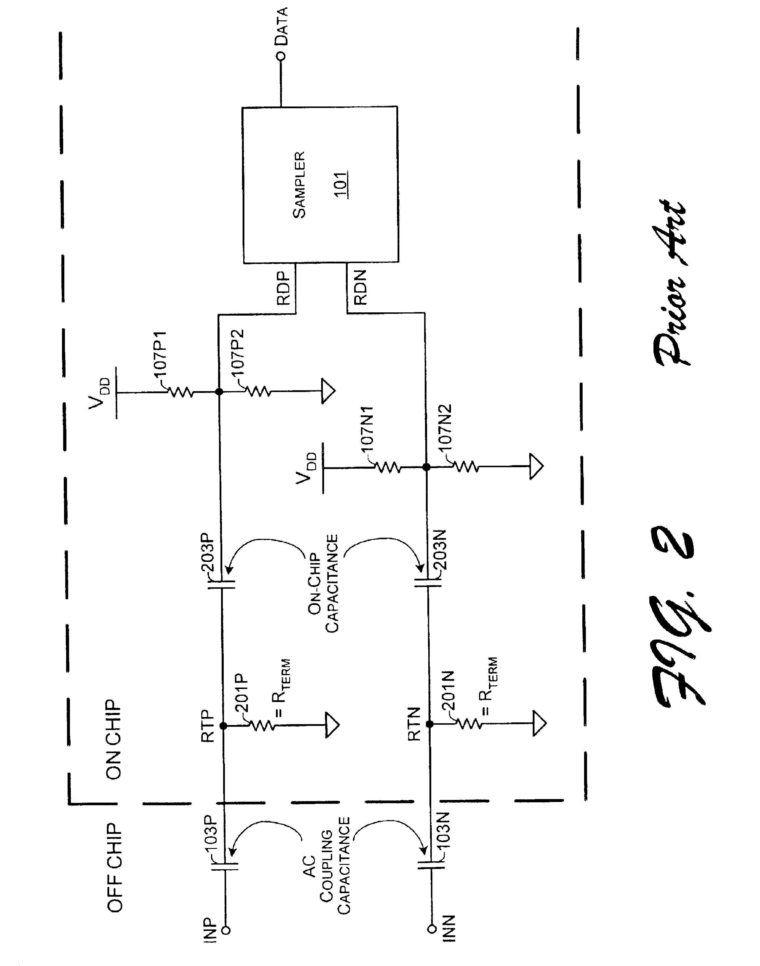
a signal reception and ground termination technology, applied in the field of signal reception, can solve the problems of not performing well, samplers b>101/b> tend not to operate in an optimal fashion with common mode voltage, and the signal input receiver of fig. 1 therefore fails to meet the specifications of pci express

Inactive Publication Date: 2005-02-15
RAMBUS INC
View PDF4 Cites 102 Cited by
  • Summary
  • Abstract
  • Description
  • Claims
  • Application Information

AI Technical Summary

Problems solved by technology

Also, sampler 101 is typically designed with transistors that do not perform well at input common mode voltages near, much less below, zero volts.
The signal input receiver of FIG. 1 therefore fails to meet the specifications for PCI Express.
Moreover as noted above, even if nodes RTP and RTN were forced to zero volts, samplers 101 tend not to operate in an optimum fashion with common mode voltages that are not at a sufficiently positive level.
Unfortunately, there are drawbacks to using the on-chip capacitance as implemented with capacitors 203P and 203N.
Unfortunately, not only does each such transistor occupy a large surface area of the IC chip, but this approach places another constraint on sampler 101.
Unfortunately, because the capacitance value of such capacitors is equal to a few hundred pico-farads, the dielectric is thick relative to a gate ox...

Method used


Image

  • Method and apparatus for signal reception using ground termination and/or non-ground termination
  • Method and apparatus for signal reception using ground termination and/or non-ground termination
  • Method and apparatus for signal reception using ground termination and/or non-ground termination

Examples


Embodiment Construction

FIG. 3 is a block diagram that illustrates signaling across a channel between exemplary electronic units. These electronic units include an exemplary transmitting unit (TU) 302 and an exemplary receiving unit (RU) 306. TU 302 sends a signal 304 to RU 306 across the illustrated channel. Although only a single signal 304 is shown being transmitted from TU 302 to RU 306, in many cases there may be multiple signals transmitted from TU 302 to RU 306 using signal output driver circuitry (at TU 302) and signal input receiver circuitry (at RU 306). Additionally, one or more signals may be transmitted from RU 306 to TU 302, as indicated by the dashed arrow representing optional signal(s) 308.

The TU 302 may comprise a transmitter, a circuit, a portion of a circuit, an IC chip, a PCB, an electronic subsystem, a computer, and so forth. Similarly, RU 306 may comprise a receiver, a circuit, a portion of a circuit, an IC chip, a PCB, an electronic subsystem, a computer, and so forth. By way of exa...


PUM


Abstract

Receiving units with inputs that may be ground-terminated and with inputs that are selectively ground-terminated or non-ground terminated are enabled with signal level shifting and a termination mode selection input. In a first exemplary implementation, a receiving unit is capable of having ground-terminated inputs. However, common mode voltage of the signal that is input to decoding data recovery circuitry is above ground because the input signal may be level shifted in between the ground-terminated inputs and the decoding data recovery circuitry. In a second exemplary implementation, a mode selection is accomplished by switching a voltage divider into operation and bypassing a level shifter for a non-ground terminated mode. For a ground terminated mode, the voltage divider is switched out of operation and the level shifter is switched into operation for its signal output to be decoded. Pre-amplification may also be employed to improve signal strength.

Description

TECHNICAL FIELDThis disclosure relates in general to the field of signal reception in a ground termination mode and / or in a non-ground termination mode, and in particular, by way of example but not limitation, to implementing (i) a signal receiving unit having ground-terminated inputs and accommodation for data recovery circuitry that is designed to prefer positive common mode voltages and / or (ii) a multi-mode signal receiving unit that is adapted to selectively provide ground-terminated inputs and non-ground-terminated inputs for routing to data recovery circuitry.BACKGROUNDElectronic signaling within and between integrated circuits (ICs) is accomplished using many different formats, standards, and approaches. Each of these electronic signaling types may be based on and / or reflect a voltage range or swings thereof, an absolute current or changes thereto, a signaling speed or frequency modulation, a combination thereof, and so forth. The various circuits that are used to implement s...

Claims


Application Information

Patent Timeline
IPC IPC(8): H03K19/0175H03K5/00H03K19/003H03K5/01H03K5/003H04L25/02
CPCH03K5/003H04L25/0292H04L25/0272
Inventor FRANS, YOHAN U.NGUYEN, NHAT M.WANG, YUEYONG
Owner RAMBUS INC
Why Eureka
Try Eureka