
High power slab type gas laser

a gas laser and slab technology, applied in the field of gas lasers, can solve the problems of reducing the accuracy requirements regarding the laser head design, reducing the volume of the laser active region, and not allowing to stabilize the fundamental transverse waveguide radiation, etc., and achieves fine focus, high output power, and high spectral mode purity.

Inactive Publication Date: 2005-02-15
GOSUDARSTVENNOYE PREDPRIYATIE NAUCHNOISSLEDOVATELSKY INST LAZERNOY FIZIKI +1
View PDF12 Cites 15 Cited by
  • Summary
  • Abstract
  • Description
  • Claims
  • Application Information

AI Technical Summary

Benefits of technology

In view of the above-mentioned problems and disadvantages of the prior art, it is therefore an object of the present invention to provide a gas laser of compact structure and high output power that is capable of outputting a laser beam of high spectral mode purity that may be finely focused for further applications.
This embodiment allows the RF power to be optimally supplied to the discharge region, thereby taking into account the varying gap height of the discharge region due to the electrode curvature.

Problems solved by technology

Due to the restriction with respect to the gap distance along the narrow axis to about 2 mm to generate a fundamental mode radiation, the volume of the laser active region, and thus the available output power, is also limited.
Additionally to the general permission for this frequency for technological applications, the use of this RF frequency remarkably simplifies the RF generator and reduces the accuracy requirements regarding the laser head design.
As previously explained, however, the arrangement of the discharge region having two plane-parallel electrodes defining a height of 4 mm and more does not allow to stabilize the fundamental transverse waveguide radiation mode without additionally excite the third radiation mode with an intensity comparable to the fundamental radiation mode.
However, as is shown in “The Characteristics and Stability of High Power Transverse Radio Frequency Discharges for Waveguide CO2 Slab Laser Excitation”, by P. Vitruck, D. R. Hall, H. J. Baker, Applied Physics Letters, Vol. 25, pages 1767-1776, 1992, the employment of radio frequencies lower than approximately 35 MHz is disadvantageous in that the discharge transformation becomes increasingly unstable since, for high power applications, the large specific energy deposition leads to large discharge currents and a high average electron energy.
A further problem involved in conventional high power gas slab lasers of the slab type resides in the fact that for a high generation efficiency, the resonator mirrors are required to be closely positioned at the longitudinal ends of the electrodes to reduce the resonator losses owing to the coupling losses of the radiation propagating from the free space between the electrode and the resonator mirror back into the discharge region.
The closely arranged resonator mirrors, however, are then exposed to plasma ions, and the interaction of the plasma ions with the mirror surfaces significantly reduces the lifetime of the mirrors while also leading to a gradual reduction of the laser output power.

Method used


Image

  • High power slab type gas laser
  • High power slab type gas laser
  • High power slab type gas laser

Examples


Embodiment Construction

With reference to FIGS. 1-6 the basic concept of the present invention will be explained.

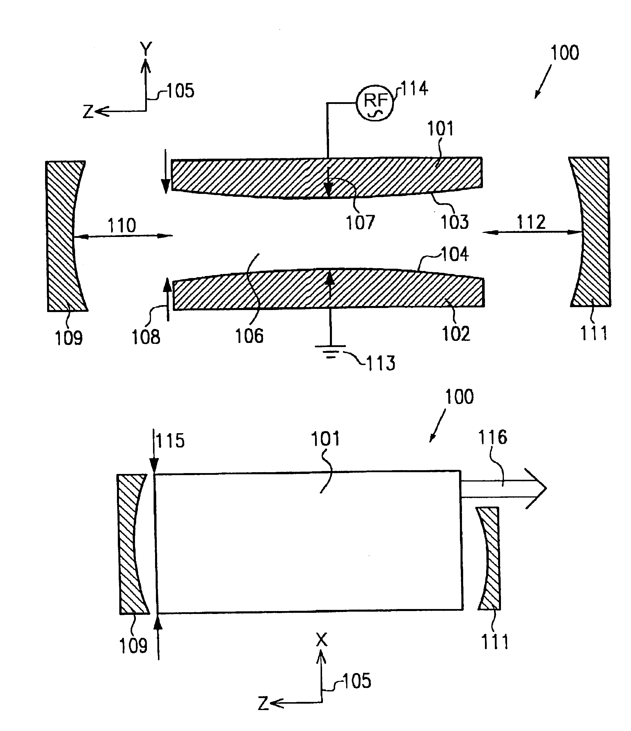
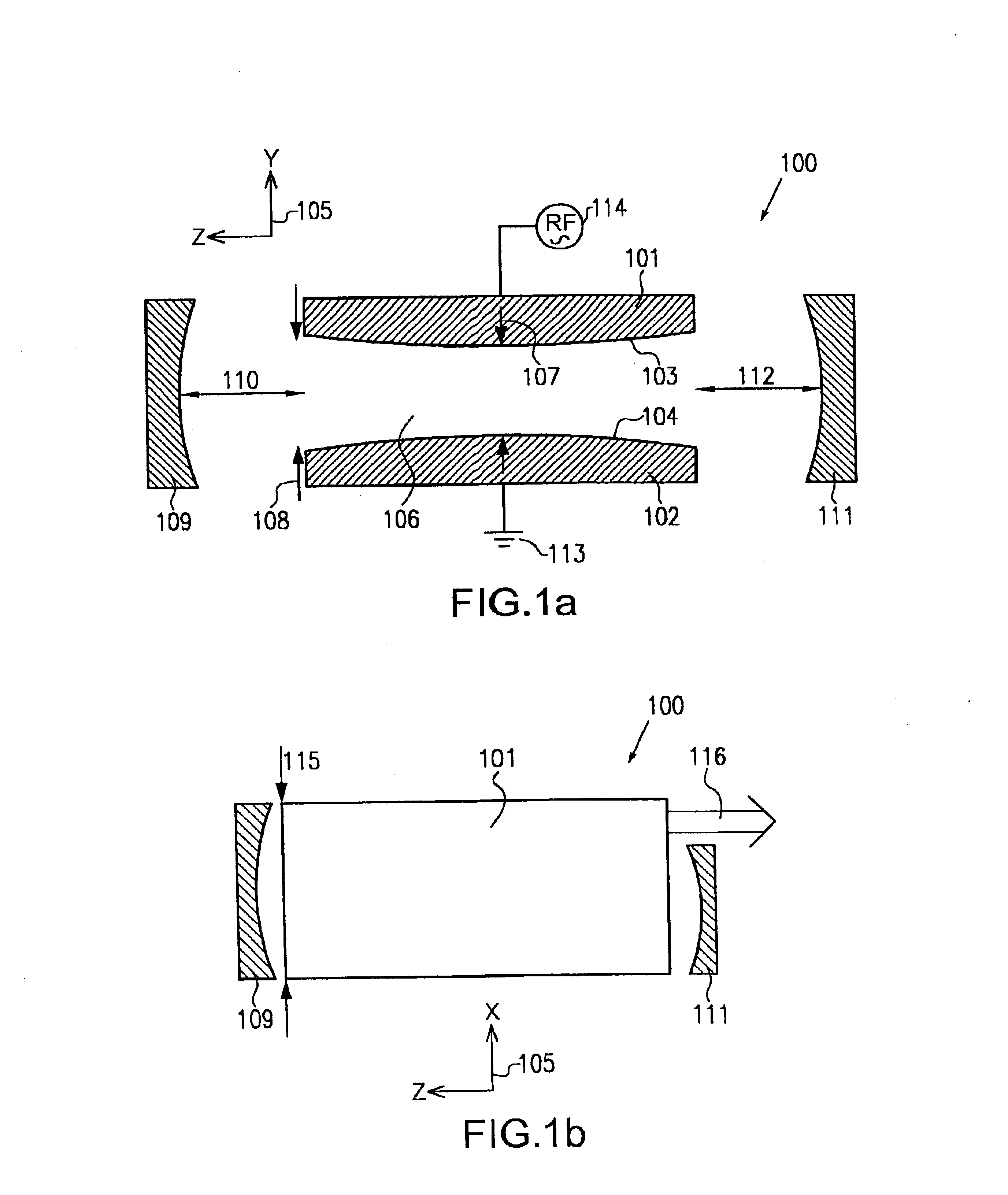
In FIG. 1a a schematic cross-sectional side view of a first embodiment in accordance with the present invention is shown.

In FIG. 1, a gas laser device 100 comprises a pair of elongated electrodes 101 and 102 having surfaces 103 and 104, respectively, that are arranged in spaced relationship so as to face each other. The surfaces 103 and 104 exhibit a curvature in the longitudinal axis indicated by the Z axis of the coordinate system 105. The surfaces 103 and 104 define a discharge region 106 with a minimum gap distance 107 and a maximum gap distance 108. The discharge region 106 is filled with a laser active gas comprising, for instance, a mixture of CO2:N2:He:Xe=1:1:6:0.4. A pressure of the laser active gas may be maintained at a value of, for example, 50 Torrs with corresponding pump means that, for the sake of simplicity, are not shown in the Figure.

A first mirror 109 spaced apart with respec...


PUM


Abstract

A gas laser comprises a pair of elongated electrodes arranged to define a discharge region between two opposing surfaces of said elongated electrodes, wherein the discharge region defines a longitudinal axis, a wide axis and a narrow axis. The gas laser further includes a lasing gas disposed in said discharge region and an excitation means for energizing the electrodes to excite the lasing gas. A first mirror is arranged in front of a first end of the pair of elongated electrodes, wherein the first mirror is spaced apart from the first end along the longitudinal axis by a first distance, and a second mirror is arranged in front of a second end of the pair of elongated electrodes. Moreover, the two opposing electrode surfaces define an electrode curvature, respectively, that is adapted such that a wave front of the a fundamental transverse radiation mode with respect to the narrow axis substantially coincides with a mirror curvature of the first mirror at the first distance.

Description

BACKGROUND OF THE INVENTIONThe present invention relates to a gas laser comprising a pair of elongated electrodes arranged to define a discharge region between two opposing surfaces of said elongated electrodes, wherein the discharge region defines a longitudinal axis, a wide axis, and a narrow axis. The gas laser further comprises a lasing gas disposed in said discharge region, an excitation means for energizing the electrodes to excite the lasing gas, a first mirror arranged in front of a first end of the pair of elongated electrodes, wherein the first mirror has a first distance from the first end along the longitudinal axis. Furthermore, the gas laser comprises a second mirror arranged in front of a second end of the pair of elongated electrodes.Gas lasers like the one indicated above are generally known in the art and are commonly referred to as gas slab lasers. Recently, this type of gas laser has steadily gained in importance due to fact that this laser device is compact yet ...

Claims


Application Information

Patent Timeline
IPC IPC(8): H01S3/038H01S3/06H01S3/08H01S3/07
CPCH01S3/0385H01S3/08081H01S3/076
Inventor DUTOV, ALEXANDER IVANOVICHSEMENOV, VICTORKULESHOV, ALEXEY A.NOVOSELOV, NIKOLAY A.SOKOLOV, ALEXANDER A.
Owner GOSUDARSTVENNOYE PREDPRIYATIE NAUCHNOISSLEDOVATELSKY INST LAZERNOY FIZIKI
Learn More