
Device with at least one laser sensor and method of operating a laser sensor

a laser sensor and laser sensor technology, applied in the direction of mechanical roughness/irregularity measurement, distance measurement, instruments, etc., can solve the problems of increasing the risk of people being further reduced, the single-point scan of the front traffic space is not sufficient, and the laser sensor has considerable power loss, etc., to achieve the effect of reducing the risk of peopl

Inactive Publication Date: 2005-02-15
VOLKSWAGEN AG
View PDF7 Cites 27 Cited by
  • Summary
  • Abstract
  • Description
  • Claims
  • Application Information

AI Technical Summary

Benefits of technology

The present invention provides a laser sensor that can adjust the power output of the laser beam based on the direction it is directed. This helps to reduce the average power input of the sensor, which can lead to a smaller power supply and cooling system, as well as increased eye safety. The laser sensor's beam power can be continuously varied, and its maximum power and power characteristic across a scanning area can be selected based on the vehicle speed or the detected object's distance and type (living or article). This allows for a more adaptable and safe laser beam for different driving situations.

Problems solved by technology

In the case of automatic ranging systems or lane-change assistance devices, a fixed, single-point scan of the front traffic space is not sufficient, but rather, a certain sector must at least be scanned in order to reliably detect an object.
However, this results in considerable power losses in the laser sensor, which must be supplied by an energy source and must be dissipated in the form of heat, using appropriate cooling measures.
If passive cooling measures, such as heat sinks, do not suffice in this case, then active cooling systems requiring additional energy must be used.
On the other hand, the power output of laser sensors is limited by safety requirements for the benefit of persons in the vicinity of the vehicle, who can be struck by the laser beams and receive an eye injury due to a reflex.
Therefore, an object appearing suddenly is struck by an unnecessarily intense scanning beam.

Method used


Image

  • Device with at least one laser sensor and method of operating a laser sensor
  • Device with at least one laser sensor and method of operating a laser sensor

Examples


Embodiment Construction

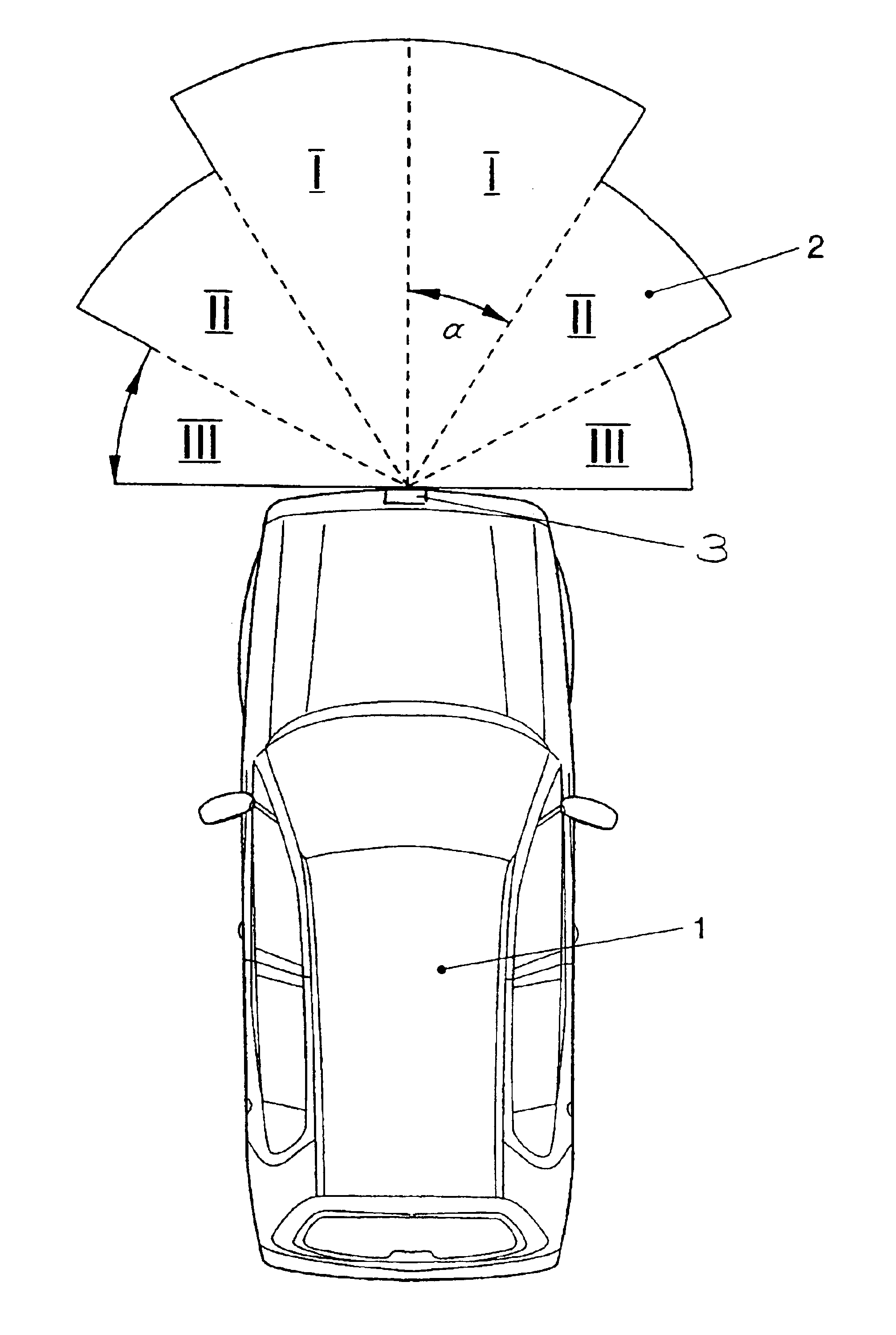
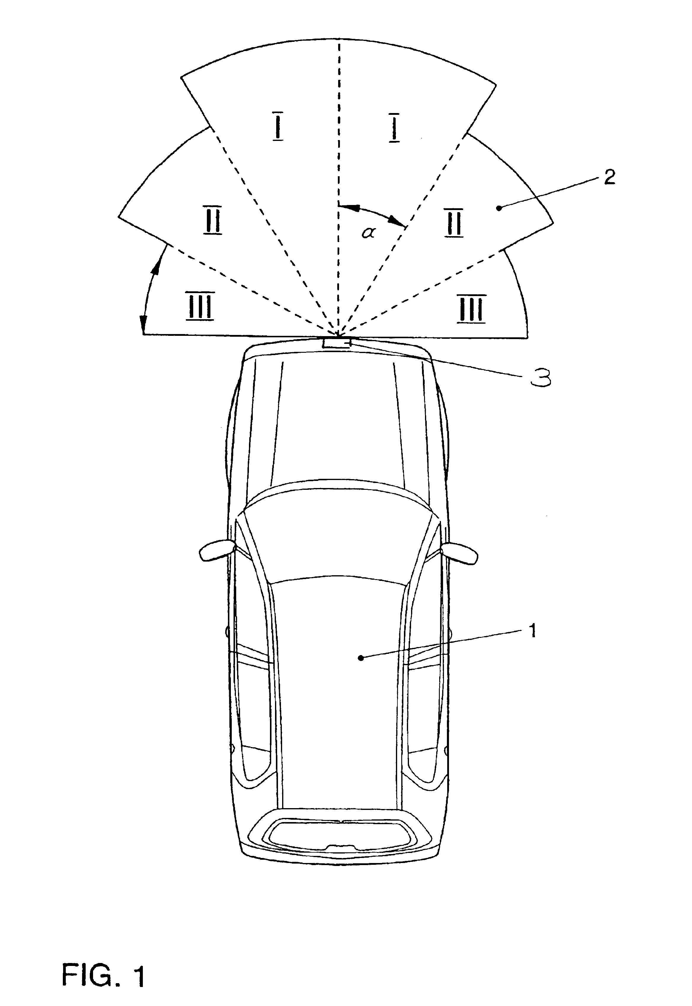
The present invention is explained below in detail, using an example embodiment. FIG. 1 illustrates a scanning area of a laser-scan distance-sensing system.

Illustrated in FIG. 1 is a motor vehicle 1 having a scanning laser sensor 3 positioned in the front area of motor vehicle 1, the scanning laser sensor being, for example, a component of an automatic ranging system and a lane-change assistance device. Laser sensor 3 includes a transmitter unit, which emits laser radiation, and a receiving device, which receives laser radiation reflected by objects or obstacles, and may evaluate it according to propagation time and angle of incidence. In addition, laser sensor 3 includes a device configured to horizontally sweep the laser beam across a scanning range 2, which is 180° in the illustrated example embodiment of the present invention. However, scanning ranges of up to 360° are also possible. The device configured to sweep the laser beam may either swing the laser as a whole or may be in...


PUM


Abstract

A device for a motor vehicle includes at least one laser sensor. The laser sensor includes a device configured to sweep a scanning area with at least one laser beam emitted by the laser sensor and a power supply device for the laser sensor. In a method for operating a laser sensor in a scanning area with at least one laser beam, the power of the laser beam emitted by the laser sensor is varied in accordance with its direction of radiation.

Description

FIELD OF THE INVENTIONThe present invention relates to a device for a motor vehicle, having at least one laser sensor, the laser sensor including a device for sweeping, in a scanning area, at least one laser beam that may be emitted by the laser sensor, and including a power supply for the laser sensor. The present invention also relates to a method for operating a laser sensor of a motor vehicle, in a scanning area, using at least one laser beam.BACKGROUND INFORMATIONIn automotive engineering, information regarding the presence, the distance, and possibly the speed of objects is particularly needed for various control systems. Examples of such control systems or driver-assistance devices include automatic ranging, a pre-crash sensory system that triggers the airbags in a timely manner, lane-changing devices, or park-distance control devices. In this context, various distance sensors based on different physical principles are, in turn, conventional, such as laser, radar, or ultrasou...

Claims


Application Information

Patent Timeline
Patent Type & Authority Patents(United States)
IPC IPC(8): G01S17/93G01S17/00G01S7/48G08G1/16G01S17/931
CPCG01S7/48G08G1/16G01S17/936G08G1/166G08G1/167G01S17/931
Inventor BASTIAN, ANDREASSCHNEIDER, ARTHUR
Owner VOLKSWAGEN AG
Learn More