Multi-link receiver for processing multiple data streams

a multi-link receiver and data stream technology, applied in the field of information transfer systems, can solve the problems of inter-pair skew, serialized information can take substantially longer than sending parallel information, and cannot be delivered without its own,

Inactive Publication Date: 2005-02-15
PIXELWORKS SEMICON TECH SHANGHAI CO LTD
View PDF15 Cites 53 Cited by
  • Summary
  • Abstract
  • Description
  • Claims
  • Application Information

AI Technical Summary

Benefits of technology

In accordance with another embodiment, the receiver further comprises an adjustable delay element and a delay adjustment control. The adjustable delay element receives a clock signal and imposes a variable delay thereon to derive the reference signal used by the signal generator to generate the latching control signals. The magnitude of the variable delay imposed by the adjustable delay element is controlled by the delay adjustment control. In one embodiment, the variable delay is set such that the reference signal is made to coincide approximately with the midpoint of a data period of the data stream. With the ability to adjust the variable delay imposed by the adjustable delay element, the receiver is able to derive a proper reference signal regardless of the alignment of the data stream.

Problems solved by technology

Because of this, sending serialized information can take substantially longer than sending parallel information.
The multi-channel implementation of FIG. 1 does not come without its problems, however.
One of its major problems is the phenomenon known as inter-pair skew.
This misalignment makes it difficult for the receiver 104 to recover data from both data streams dr(1), dr(n).
When multiple data streams arrive at a receiver out of alignment, it is impossible for a single clock signal to maintain proper alignment with all of the data streams.
In general, inter-pair skew makes recovering data from multiple data streams significantly more difficult and complex.
However, this solution does not come without significant drawbacks.
For one thing, generating and managing multiple latching control signals per data period imposes significant additional overhead, both in terms of generating additional signals and of providing additional storage (since each sampled value needs to be stored).
As a result, there is significant redundancy in an oversampling system.
Also, notice that the sampling position is not optimal.
This may lead to data errors.
In addition and perhaps most significantly, oversampling imposes a practical limit on how quickly data can be transmitted.
By requiring a small delay (time constant TC) between successive latching control signals, oversampling limits the rate at which data can be practically sent in a data stream.
As a general rule, the faster an element processes a signal (and hence, the shorter the delay), the more difficult and expensive the element is to manufacture.
Due to constraints such as cost and technological limitations, there is a practical limit on how quickly a delay element can process a signal, and hence, how small a delay can be.
This aspect of oversampling makes it an unattractive solution in many implementations.
While the PLL implementation provides a possible solution to the inter-pair skew problem, it comes with some significant drawbacks.
First, because it uses PLL's, jitter performance is less than optimal, and power consumption is relatively high due to the nature of PLL's.
In addition and more significantly, the PLL implementation, like oversampling, can significantly limit the rate at which data can be transferred in a data stream.
Thus, even though it is not as limiting as the oversampling implementation, the PLL implementation still does impose a significant limit on the rate at which data can be sent in a data stream.

Method used


Image

  • Multi-link receiver for processing multiple data streams
  • Multi-link receiver for processing multiple data streams
  • Multi-link receiver for processing multiple data streams

Examples


Embodiment Construction

)

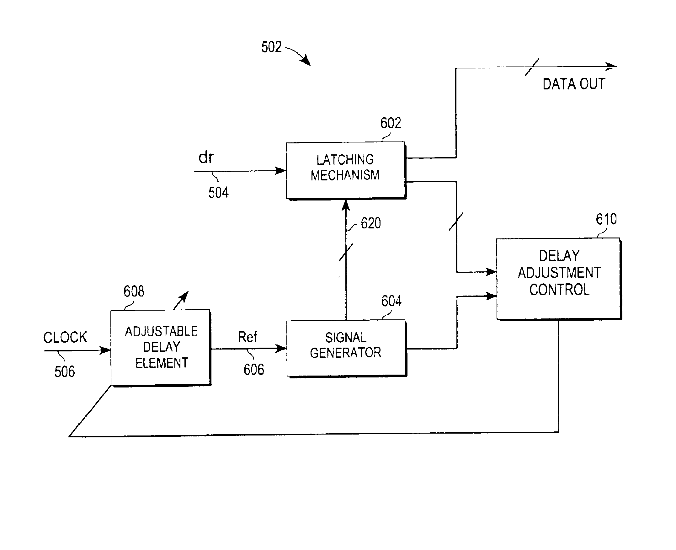
Throughout the following description, the terms “synchronized” and “aligned” will be used. To facilitate a complete understanding of the description, these terms will now be defined. When a first signal is referred to as being synchronized with a second signal, it is meant that the first signal has the same period or an integral multiple of the period of the second signal. For example, if the second signal has a period of T, then the first signal is synchronized with the second signal if the first signal has a period of T, 2T, 3T, 4T, and so forth. As an example, both the Clock signal and the control signal C1 of FIG. 4 are synchronized with the data stream dr.

Just because two signals are synchronized does not mean that they are aligned, however. For a first signal to be aligned with a second signal, all of the transitions of the first signal need to coincide with transitions of the second signal. If any transition of the first signal does not coincide with a transition of the seco...


PUM


Abstract

A multi-link receiving mechanism (MRM) is disclosed comprising a plurality of receivers. Each receiver receives a separate data stream, and all receivers receive the same clock signal. The data streams may arrive at the MRM out of alignment relative to each other (i.e. may have inter-pair skew), and the clock signal need not be aligned with any of the data streams. In response to the clock signal and the data stream, each receiver delays the clock signal by a variable delay to derive a reference signal. This is done to achieve a desired relative alignment between the data stream and the reference signal. Once the reference signal is derived, it is used by the receiver to generate a plurality of latching control signals. These latching control signals are thereafter used by the receiver to latch all of the data units of the data stream. Data from the data stream is thus recovered. Each of the receivers operates in the manner described to recover data from each of the data streams. Because each receiver individually adjusts for the varying alignments of the various data streams, the MRM is able to accommodate and properly process data streams with inter-pair skew.

Description

FIELD OF THE INVENTIONThis invention relates generally to information transfer systems, and more particularly to an improved multi-link receiving mechanism for concurrently processing multiple data streams.BACKGROUNDIn the information transfer systems of today, speed is a major if not the primary consideration. The faster information can be transferred from one location to another, the better. Because of the need for increased speed performance, a number of techniques have been developed to facilitate and to accelerate data transfer.Typically, information is transferred from a starting location to a destination by first converting the information from a parallel format to a serialized format. Then, the serialized information is transmitted as a data stream across a transmission medium such a coaxial cable, a twisted pair cable, or a fiber optic cable, to the destination. At the destination, a receiver receives the data stream, and processes it to convert the information back into a ...

Claims


Application Information

Patent Timeline
Patent Type & Authority Patents(United States)
IPC IPC(8): G06F1/12G06F1/04H04L7/033
CPCH04L7/0037H04L7/033
Inventor LIANG, GUOJIN
Owner PIXELWORKS SEMICON TECH SHANGHAI CO LTD
Why Eureka
Try Eureka