Orifice reducer for container neck

a technology of orifice reducer and container neck, which is applied in the field of container necks, can solve the problems of relatively large diameter of the orifice reducer, the circumferential wall cannot fit cleanly into the opening, and the conventional orifice reducer can be relatively difficult to insert in the container, so as to reduce the thickness, reduce the hoop strength, and increase flexibility

Inactive Publication Date: 2005-02-22
ACCESS BUSINESS GRP INT LLC
View PDF22 Cites 8 Cited by
  • Summary
  • Abstract
  • Description
  • Claims
  • Application Information

AI Technical Summary

Benefits of technology

The aforementioned problems are overcome by the present invention wherein an orifice reducer is provided with a circumferential wall that includes vertically extending regions of reduced thickness. The reduced regions provide “crumple” zones that permit the orifice reducer to collapse in a controlled manner when inserted

Problems solved by technology

In addition, several methods of forming plastic containers, such as injection blow molding and extrusion blow molding, inherently result in a neck of relatively large diameter.
Conventional orifice reducers can, however, be relatively difficult to insert in containers with irregularly sized or irregularly shaped neck openings.
When a conventional orifice reducer is inserted into an irregularly sized or shaped neck opening, the circumferential wall will not fit cleanly into the opening.
The f

Method used


Image

  • Orifice reducer for container neck
  • Orifice reducer for container neck
  • Orifice reducer for container neck

Examples


Embodiment Construction

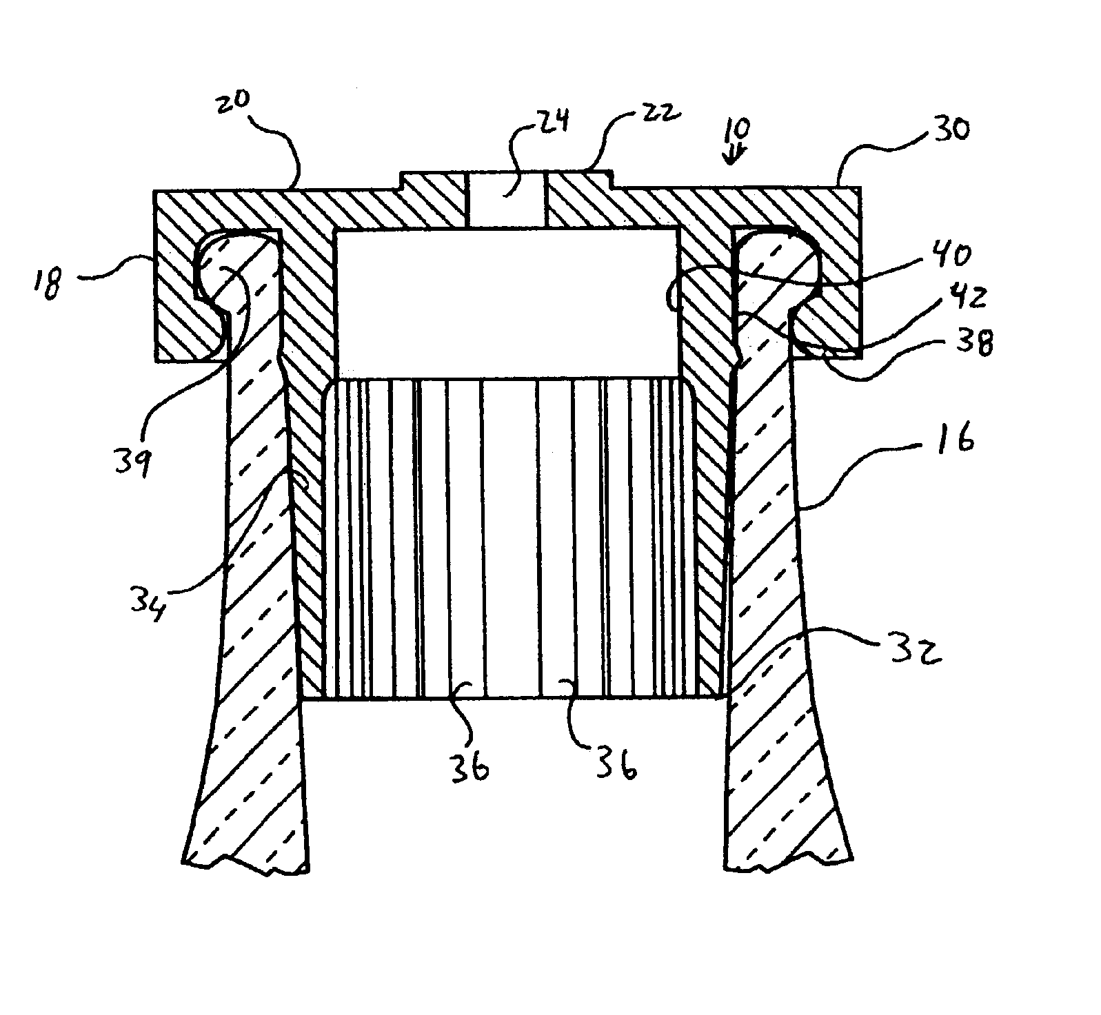
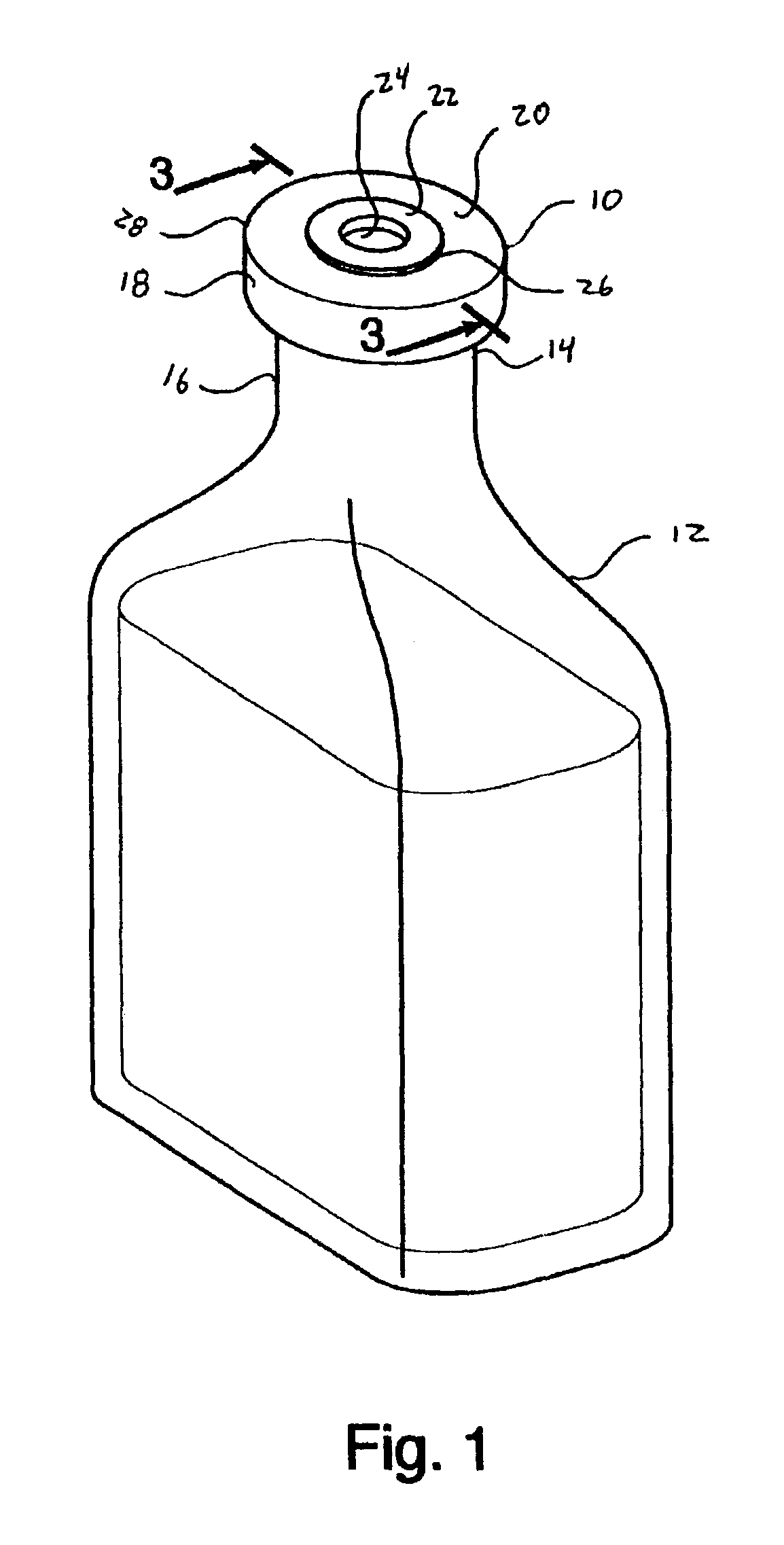
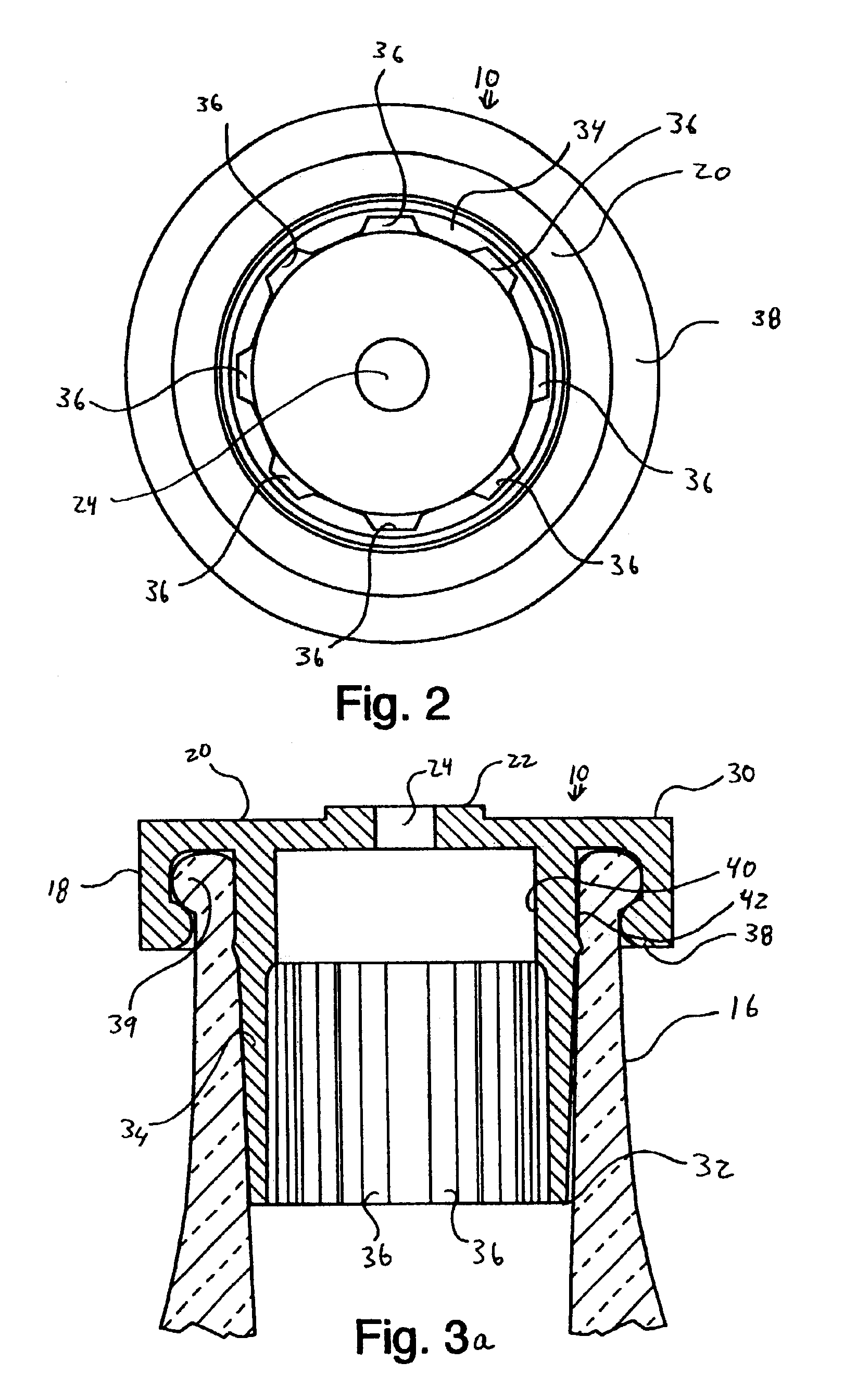
A bottle 12 incorporating an orifice reducer 10 manufactured in accordance with a preferred embodiment of the present invention is shown in FIG. 1. The bottle 12 has a top end 14 and includes a neck 16. The neck 16 defines a substantially circular opening. The orifice reducer 10 is fitted onto the bottle neck 16 and defines a relatively small aperture 24 through which the contents of the bottle are dispensed. The orifice reducer 10 includes a circumferential wall 34 that is fitted within the bottle neck 16. The circumferential wall 34 shown in FIGS. 2-5 includes reduced thickness regions (or “crumple zones”) that facilitate insertion of the orifice reducer. For purposes of disclosure, a preferred embodiment of the orifice reducer 10 is described in connection with a conventional extrusion blow molded plastic bottle. The orifice reducer can, however, be used in connection with essentially any conventional container having a neck that requires some form of orifice reduction.

The orific...


PUM


Abstract

An orifice reducer with crumple zones well suited for use with an extrusion blow molded bottle having an uneven surface finish. The device includes a circumferential wall having a number of vertically extending reduced thickness regions, preferably spaced symmetrically about the circumferential wall. The reduced thickness regions deform upon insertion of the orifice reducer into the neck of a bottle to account for irregularity of the surface finish of the bottle. This allows the orifice reducer to be more easily inserted into standard extrusion blow molded bottles.

Description

BACKGROUND OF INVENTIONThe present invention relates to containers and, more specifically, to an orifice reducer for a container neck.In general, the neck of a typical container is fairly large in relation to the overall outer diameter of the container. The relatively large orifice makes the container easier to fill during the packaging process. In addition, several methods of forming plastic containers, such as injection blow molding and extrusion blow molding, inherently result in a neck of relatively large diameter.In many applications, it is desired to have a container opening that is smaller than the neck opening in the final consumer application. A smaller neck opening typically makes it easier to control dispensing of the product, producing less wasted product. Examples of where a reduced orifice is desirable are where the container houses an expensive product that is used in relatively small quantities and where the contents of the container must be carefully dispensed in a ...

Claims


Application Information

Patent Timeline
IPC IPC(8): B65D47/06B65D1/02
CPCB65D47/06
Inventor METTLER, MARK F.DITTMER, JAY R.WHITE, MARK K.
Owner ACCESS BUSINESS GRP INT LLC
Why Eureka
Try Eureka