
Personal watercraft having a hybrid power source

a power source and personal watercraft technology, applied in the field of watercraft, can solve the problems of low limit of how much total vehicle power and amount can be supplied, -14 v systems require bulky wiring harnesses, electronics that experience voltage sags and spikes, etc., to achieve the effect of maximizing power and speed, reducing noise and environmental pollution, and reducing speed

Inactive Publication Date: 2005-02-22
BOMBARDIER RECREATIONAL PROD INC
View PDF3 Cites 59 Cited by
  • Summary
  • Abstract
  • Description
  • Claims
  • Application Information

AI Technical Summary

Benefits of technology

Therefore, one aspect of embodiments of this invention provides a watercraft with a power system that can alternately minimize noise and environmental pollution at lower speeds and maximize power and speed at higher speeds.
According to a further aspect of embodiments of the present invention, the power plant includes an internal combustion engine, and preventing the drive shaft from rotating faster than the predetermined speed includes limiting the speed of the engine.

Problems solved by technology

While such engines provide ample power for PWCs, they create both environmental and noise pollution.
Unfortunately, when PWCs are operated at low speeds such as during trolling or operating in and around people, obstacles, docks, etc., it is preferred to have an engine speed (and proportionally corresponding PWC speed) of less than 1000 rpm.
However, conventional electrical systems are 12-14V (volt), which have a low limit of how much total vehicle power and amount can be supplied, particularly in view of current standard electrical peripherals.
Such 12-14 V systems also require bulky wiring harnesses and electronics that experience voltage sags and spikes.

Method used


Image

  • Personal watercraft having a hybrid power source
  • Personal watercraft having a hybrid power source
  • Personal watercraft having a hybrid power source

Examples


Embodiment Construction

The invention is described with reference to a PWC for purposes of illustration only. However, it is to be understood that the hybrid power system described herein can be utilized in any watercraft, particularly those crafts that are powered by a jet propulsion system, such as sport boats. However, the invention is applicable to conventional propulsion systems as well, such as propeller-driven watercraft.

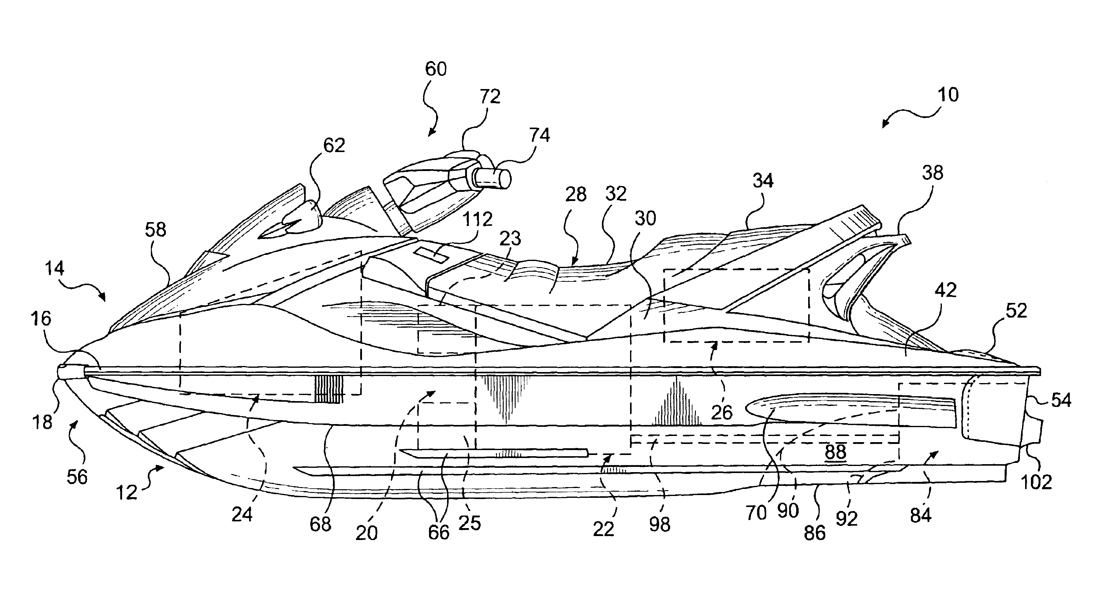
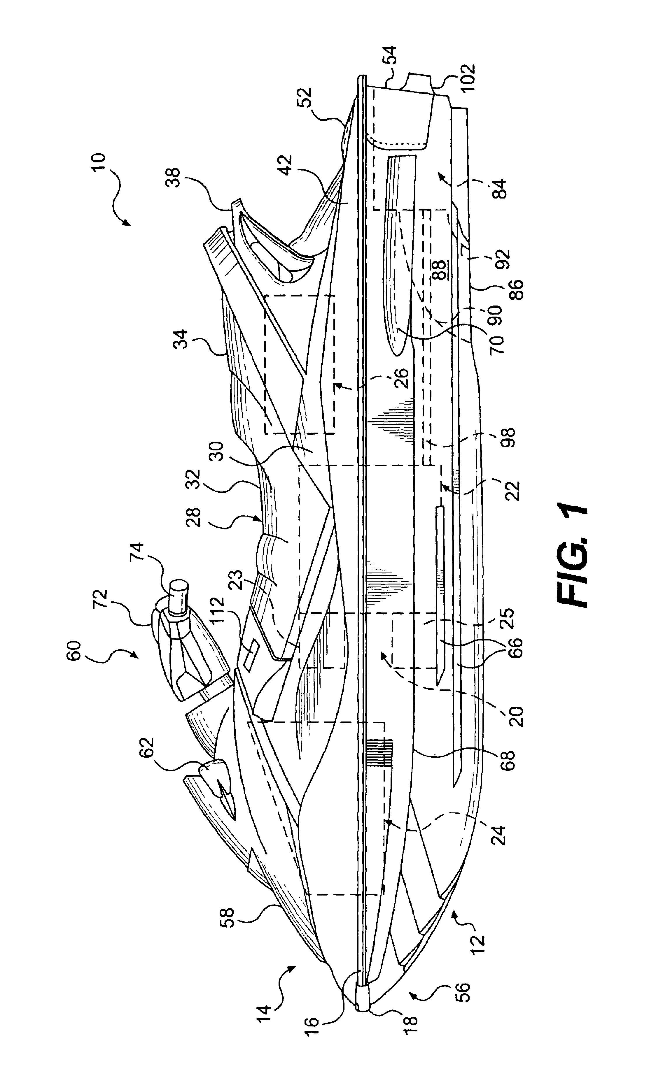
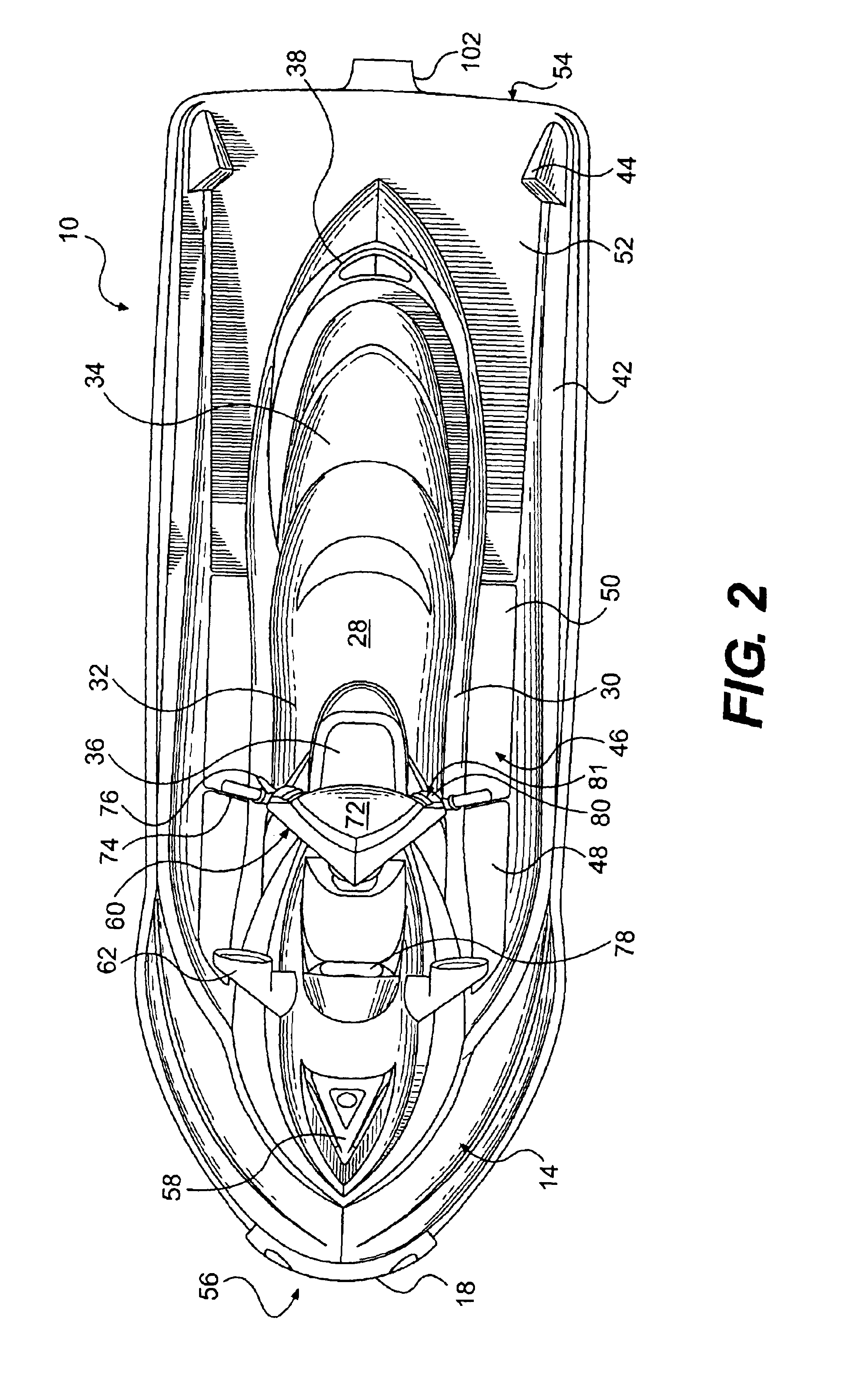
The general construction of a personal watercraft (PWC) 10 in accordance with a preferred embodiment of this invention is shown in FIGS. 1-5. The following description relates to one way of manufacturing a personal watercraft according to a preferred design. Obviously, those of ordinary skill in the watercraft art will recognize that there are other known ways of manufacturing and designing watercraft and that this invention would encompass other known ways and designs.

The watercraft 10 of FIG. 1 is made of two main parts, including a hull 12 and a deck 14. The hull 12 buoyantly sup...


PUM


Abstract

A hybrid fuel / electric powered watercraft includes an electronic turning machine (ETM), and internal combustion engine, and a propulsion system, which are operatively connected to each other, preferably via one or more clutches. An electronic control unit (ECU) controls the ETM, clutch(es), and engine. At low speeds, the ECU disengages at least one clutch and solely uses the ETM to power the propulsion unit and propel the watercraft. At high speeds, the ECU engages the clutch and uses both the engine and the ETM or just the engine to power the propulsion system. When the watercraft's battery discharges, the ECU operates the ETM in a generator mode and runs the engine to charge the battery. The watercraft can also include a shore button feature that selectively limits / governs the speed of the watercraft. A clutch may be used to avoid driving the propulsion system when the engine is idling or being started.

Description

BACKGROUND OF THE INVENTION1. Field of the InventionThis invention relates to watercraft, especially jet-powered personal watercraft (“PWC”). More specifically, the invention concerns power sources used in watercraft, such as PWCs.2. Description of Related ArtJet powered watercraft have become very popular in recent years for recreational use and for use as transportation in coastal communities. The jet, power offers high performance, which improves acceleration, handling and shallow water operation. Accordingly, jet-powered PWCs and sport boats have become common place, especially in resort areas.PWCs are typically powered by a two or four stroke internal combustion engine (ICE) that has a drive shaft operatively connected to the jet pump. While such engines provide ample power for PWCs, they create both environmental and noise pollution. Furthermore, the idle speed of a conventional ICE is generally well above 1000 rpm. Unfortunately, when PWCs are operated at low speeds such as d...

Claims


Application Information

Patent Timeline
Patent Type & Authority Patents(United States)
IPC IPC(8): B60L11/02B60L50/10B63B35/73B63H21/14B63H21/17B63H21/20
CPCB63B35/731B63H21/14B63H21/20B63H21/17B63H2021/202Y02T70/5236B63B34/10
Inventor LEBREUX, NORMANDPLANTE, RENALDBERTHIAUME, YVES
Owner BOMBARDIER RECREATIONAL PROD INC
Learn More