Segment cut honeycomb core machine

a core machine and segment technology, applied in the direction of paper/cardboard articles, chemistry apparatus and processes, lamination ancillary operations, etc., can solve the problems of insufficient cutting of core stock, etc., to reduce the “close time” of the shear, the range of thicknesses is wide, and the quality is consistent

Inactive Publication Date: 2005-02-22
WROBLEWSKI SR GEORGE T +2
View PDF3 Cites 5 Cited by
  • Summary
  • Abstract
  • Description
  • Claims
  • Application Information

AI Technical Summary

Benefits of technology

The segment cut core machine of this invention provides several operational advantages over conventional segment cut core machines. This core machine can produce honeycomb core with a wider range of thickness and with a more consistent quality. The core machine of this invention includes five basic process stations: a roll stand; a glue station; a paper feed; a take-up station; and a core cut station. The core cut station uses a vertically oriented cutting shear with a unique beveled two-piece flying blade. The flying blade has a beveled cutting face that cuts the core stock in opposite directions from the outer edges to the center of the sheet. The beveled cutting edge reduces the “close time” of the shear and allows more core stock to be advanced into the shear. The beveled flying blade also reduces wear on the shear and drive motors. The take-up station includes a relatively flat deck and a gather adjustment gate that controls the character of the slack gathered in the sheet of core stock within the take-up station. The gate transverses over the sheet of core stock and can be shifted forward and back within the gather section of the take-up section to vary the wave length and amplitude of the gather formed in the slack in the core stock. The position of the adjustment gate can be quickly and easily adjusted to address slight variation between the frequency of the shear and the speed of the paper feed.
Another advantage is that the core stock is fed directly from a paper feed into the cut station through a relatively short and flat take-up station, which reduces the overall size and footprint of the core machine and prevents damages to the sheets of laminated core stock.

Problems solved by technology

Heretofore, conventional segment cut core machines have had several operational draw backs and have generally failed to fully control the manner in which the core stock gathers within the take-up section.
Conventional segment cut core machines require extensive, time consuming mechanical adjustment to set up each operational run and to maintain uniform and consistent honeycomb core.
When too little slack is gathered, the core stock does not advance fully into the cutting mechanism.
When too much slack is gathered, the core stock jams and buckles.
Paper jams due to excess slack are often the source of operational down time.
Buckling the core stock can often damage the laminated sheet of core stock separating the individual piles of paper web.
Mechanically matching the cutting cycle to the speed of the core stock feed is also complicated by variations in the core stock.
More importantly, conventional segment cut core machines have offered little means for controlling the manner and character of the slack that gathers in the sheet of core stock within the take-up section.
Often core stock jams inside the cutting mechanism due to buckles and uneven folds created in the take-up section.
At best, a mechanical adjustment that affects the gathers in conventional core machines has been limited to simply adjusting the amount of force applied to the gathers by the tensioners.

Method used


Image

  • Segment cut honeycomb core machine
  • Segment cut honeycomb core machine
  • Segment cut honeycomb core machine

Examples


Embodiment Construction

The preferred embodiment herein described is not intended to be exhaustive or to limit the invention to the precise form disclosed. It is chosen and described to best explain the invention so that others skilled in the art might utilize its teachings.

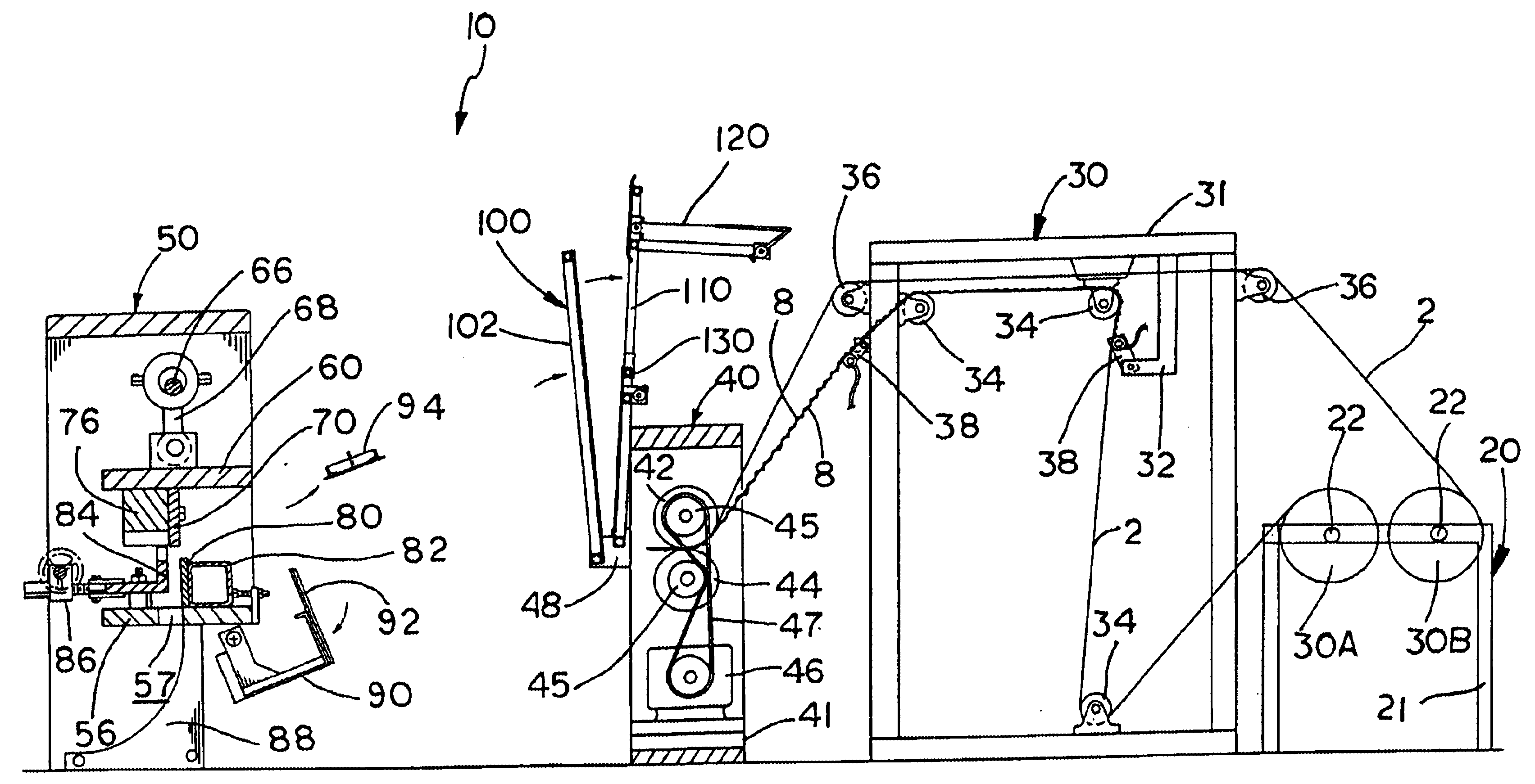
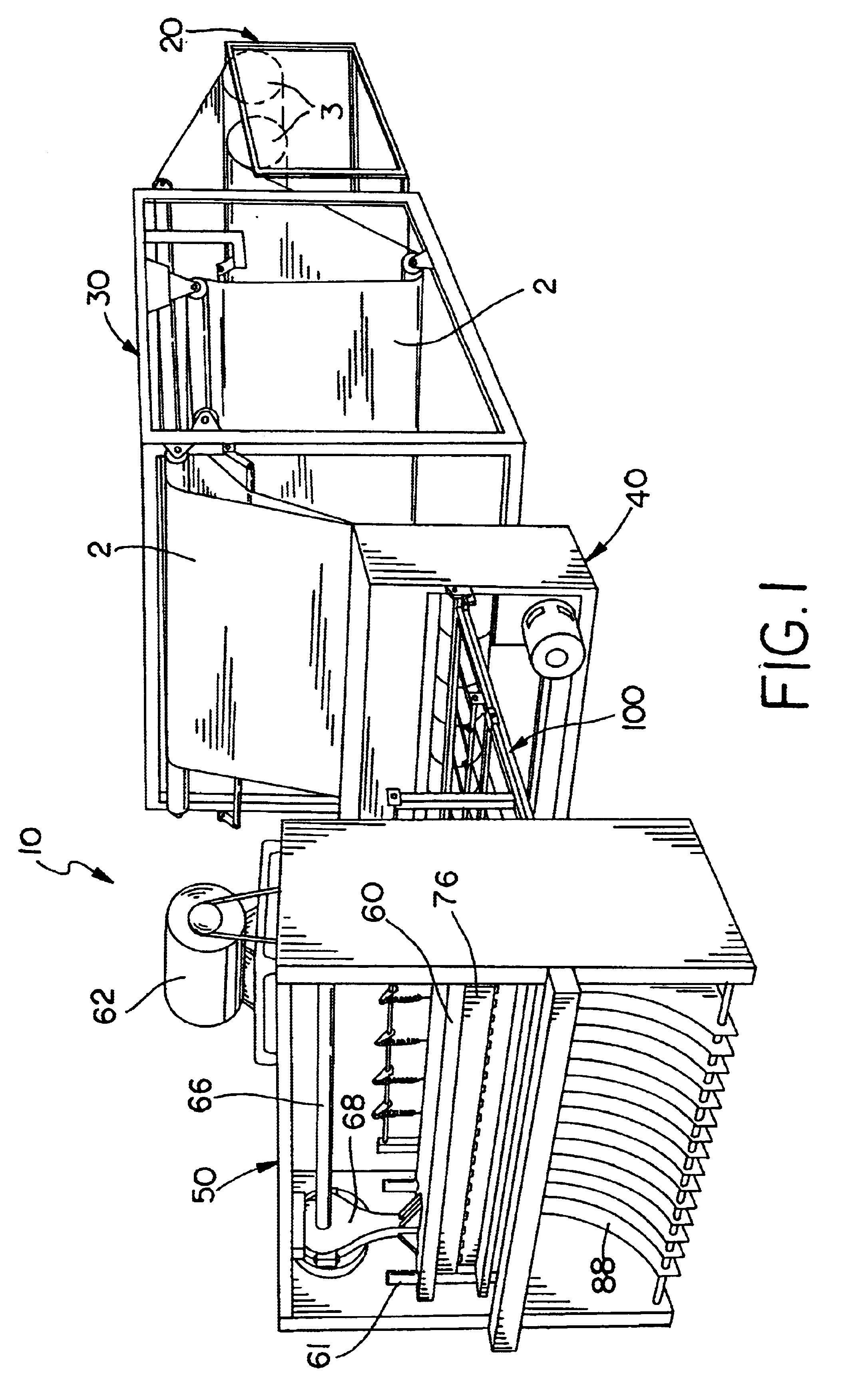
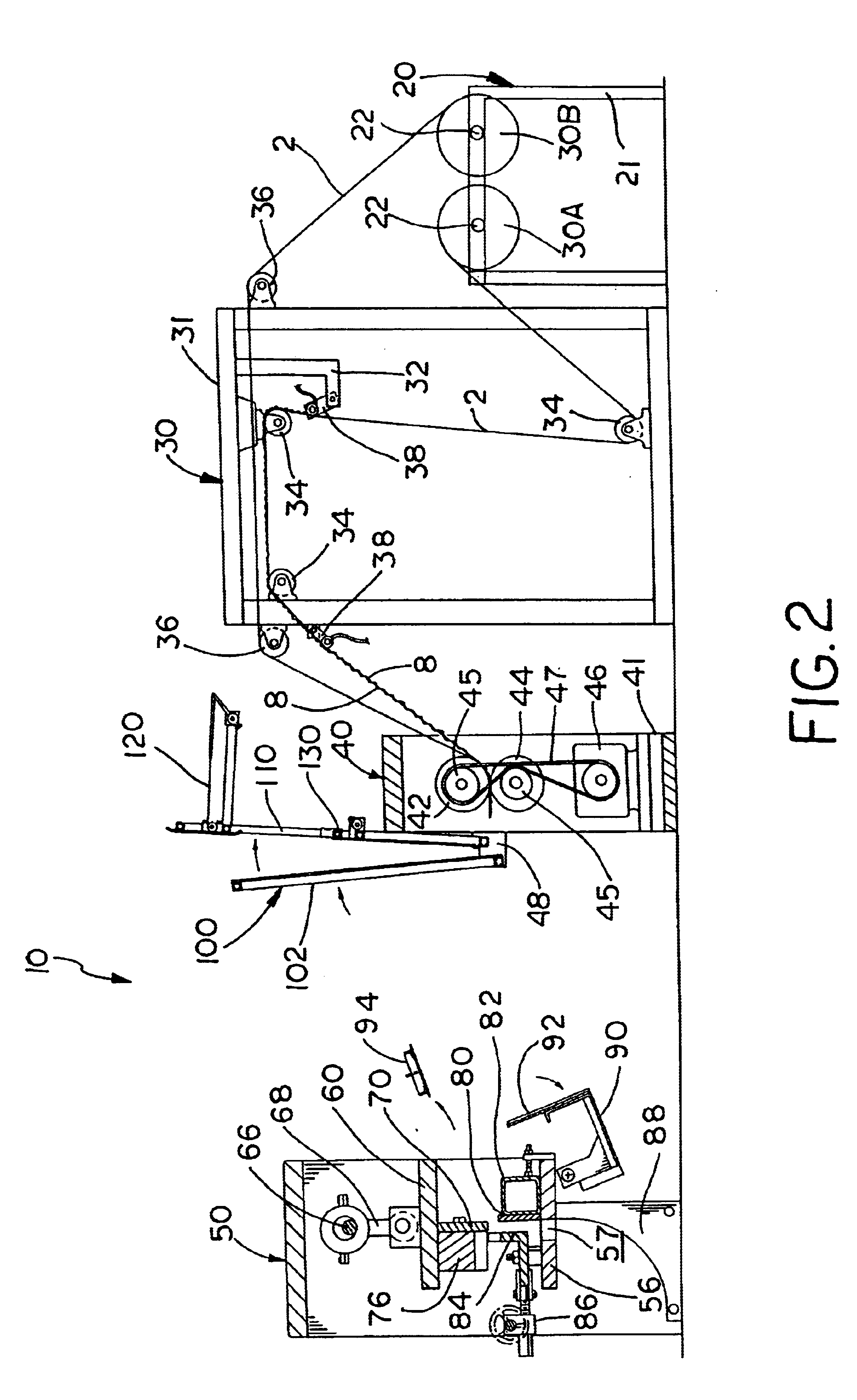
In the figures, the core machine of this invention is designated generally as reference numeral 10. The figures illustrate the core machine of this invention as a stand alone apparatus for producing continuous honeycomb core (designated generally as 6 in figures) from two sheets or webs of paper stock (designated generally as reference numeral 2 in the figures). Core machine 10 bonds the two sheets of paper stock 2 into a laminated sheet of core stock (designated as numeral 4 in figures), which is cut, stacked and compressed to form honeycomb core 6. Core machine 10 may be modified within the teachings of this invention to produce honeycomb core from a multi-ply sheet core stock. Core machine 10 is illustrated with two-ply for simplicit...


PUM

PropertyMeasurementUnit
widthsaaaaaaaaaa
widthsaaaaaaaaaa
lengthaaaaaaaaaa

Abstract

A segment cut core machine is disclosed. The core machine includes five basic process stations: a roll stand; a glue station; a paper feed; a take-up station; and a core cut station. The core cut station uses a vertically oriented cutting shear with a unique beveled two-piece flying blade. The flying blade has a beveled cutting face that cuts the core stock in opposite directions from the outer edges to the center of the sheet. The beveled cutting edge reduces the “close time” of the shear and allows more core stock to be advanced into the shear. The take-up station includes a relatively flat horizontal deck and a gather adjustment gate that controls the character of the slack gathered in the sheet of core stock within the take-up station. The gate transverses over the sheet of core stock and can be shifted forward and back within the gather section of the take-up section to vary the wave length and amplitude of the gather form in the slack in the core stock. The position of the adjustment gate can be quickly and easily adjusted to address slight variation between the frequency of the shear and the speed of the paper feed.

Description

The invention relates to a paper honeycomb core cutting machine, and in particle a segment cut honeycomb core machine that includes a vertically oriented cutting shear and an adjustable gather control mechanism.BACKGROUND OF THE INVENTIONPaper honeycomb core is a desirable building material with a growing range of applications and uses. Paper honeycomb core can be used to make strong lightweight panels and pallets. Paper honeycomb panels are constructed of an expanded honeycomb core or web sandwiched between two paper face sheets.Two types of machinery are used to produce paper honeycomb core: a rotary cut core machine and a segment cut core machine. Segment cut core machines are the most common and economical to operate. U.S. Pat. Nos. 3,257,253 and 4,133,172 illustrate and describe the basic design and operation of a segment cut core machine. Segment cut core machines produce honeycomb core from rolled sheets of paper stock. The core machine bonds multiple sheets of paper stock to...

Claims


Application Information

Patent Timeline
Patent Type & Authority Patents(United States)
IPC IPC(8): B26D1/56B26D1/01B31D3/02B31D3/00B26D1/00B26D1/08B26D7/26
CPCB26D1/0006B26D1/085B26D1/565B26D7/2614B31D3/02B26D2001/0033B26D2001/0053Y10T156/1326B26D2001/0066Y10T156/1751Y10T156/13Y10T156/1075B26D2001/006
Inventor WROBLEWSKI, SR., GEORGE T.WROBLEWSKI, JR., GEORGE T.WROBLEWSKI, ANDREW L.
Owner WROBLEWSKI SR GEORGE T
Why Eureka
Try Eureka