Composite articles

a technology of composite articles and composite foam, applied in the field of composite articles, can solve the problems of limited commercial application of these structures, high cost of carbon fiber, etc., and achieve the effects of reducing cost, high permeability, and generally low cost of carbon foam

Inactive Publication Date: 2005-02-22
SAFRAN LANDING SYSTEMS
View PDF21 Cites 9 Cited by
  • Summary
  • Abstract
  • Description
  • Claims
  • Application Information

AI Technical Summary

Benefits of technology

The methods and apparatus of this invention provide numerous advantages. For example, the cost of carbon foam is generally lower than that of carbon fibers. Therefore, methods of this invention can significantly reduce the cost of forming substantially-dense carbon / carbon composite foams. Accordingly, a broader range of applications can now be economically justified for use of carbon / carbon composites. Further, the resulting foams can have a substantially isotropic and openly-porous structure relative to that of many materials that employ fibers. Because the composite is substantially isotropic, performance of a frictional surface comprising a foam of this invention is likely to be more uniform and consistent as the friction surface wears. The ceramic composite foams also have a relatively high permeability, thereby facilitating hydraulic flow in many wet-friction applications. Moreover, distortion from machining is reduced due to the isotropic structure, thereby promoting flatness and parallelism in machined friction surfaces. The methods of this invention also can be used to produce exceptionally dense structures with over 50% solid density, while retaining open porosity.

Problems solved by technology

They are favored for use in high-end automotive transmissions but high costs have prevented widespread utilization.
Though the above-described methods are known to produce high-quality composite structures, the commercial application of these structures is limited by the high cost of carbon fibers, processing and energy consumption.
Accordingly, the application of these methods to mass-production industries, such as automobile manufacturing, has thus far been greatly limited due to economic feasibility.

Method used


Image

  • Composite articles
  • Composite articles

Examples


Embodiment Construction

A description of preferred embodiments of the invention follows. The features and other details of the method of the invention will now be more particularly described with reference to the accompanying drawing and pointed out in the claims. It will be understood that the particular embodiments of the invention are shown by way of illustration and not as limitations of the invention. The principal features of this invention can be employed in various embodiments without departing from the scope of the invention.

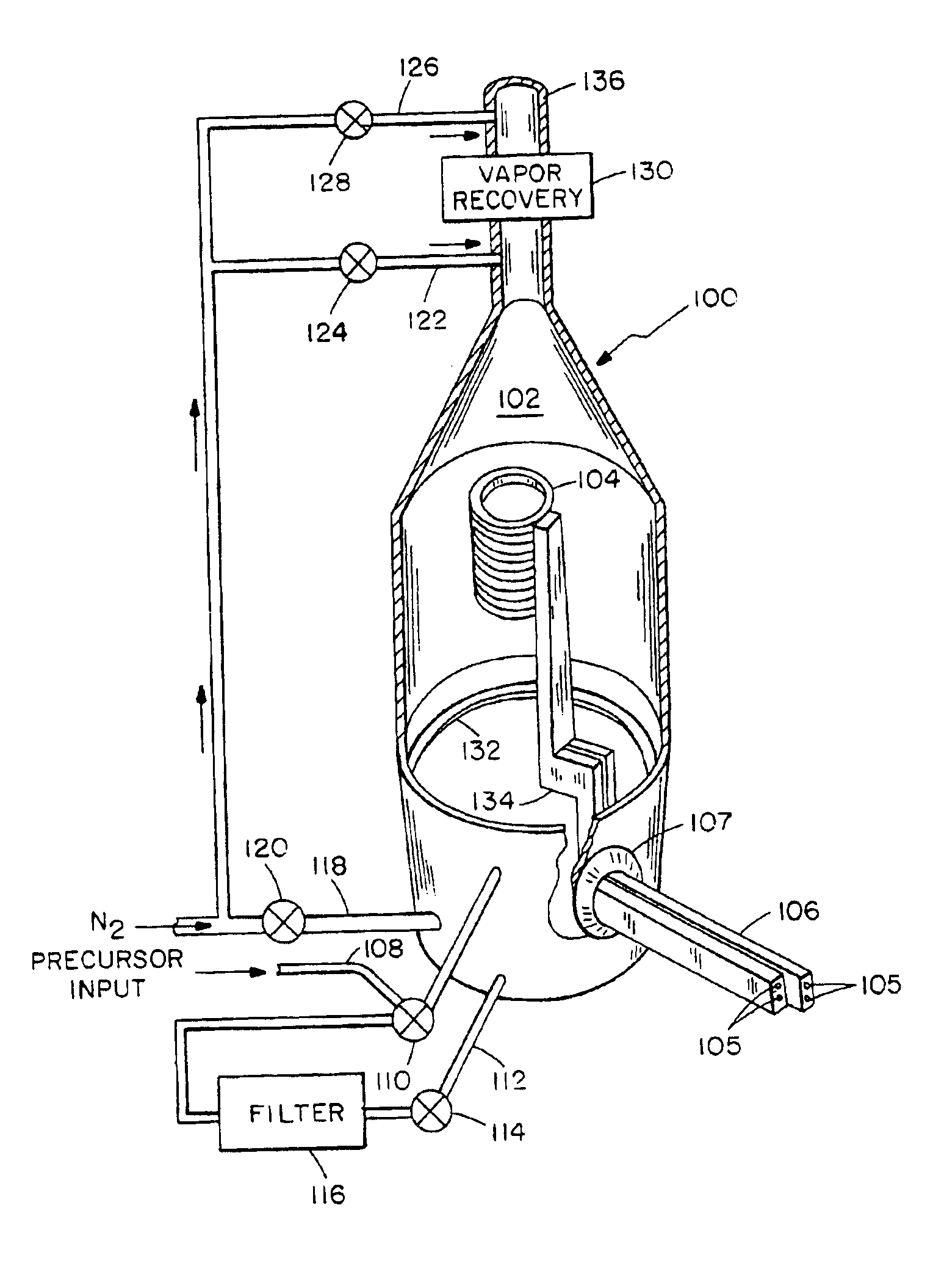
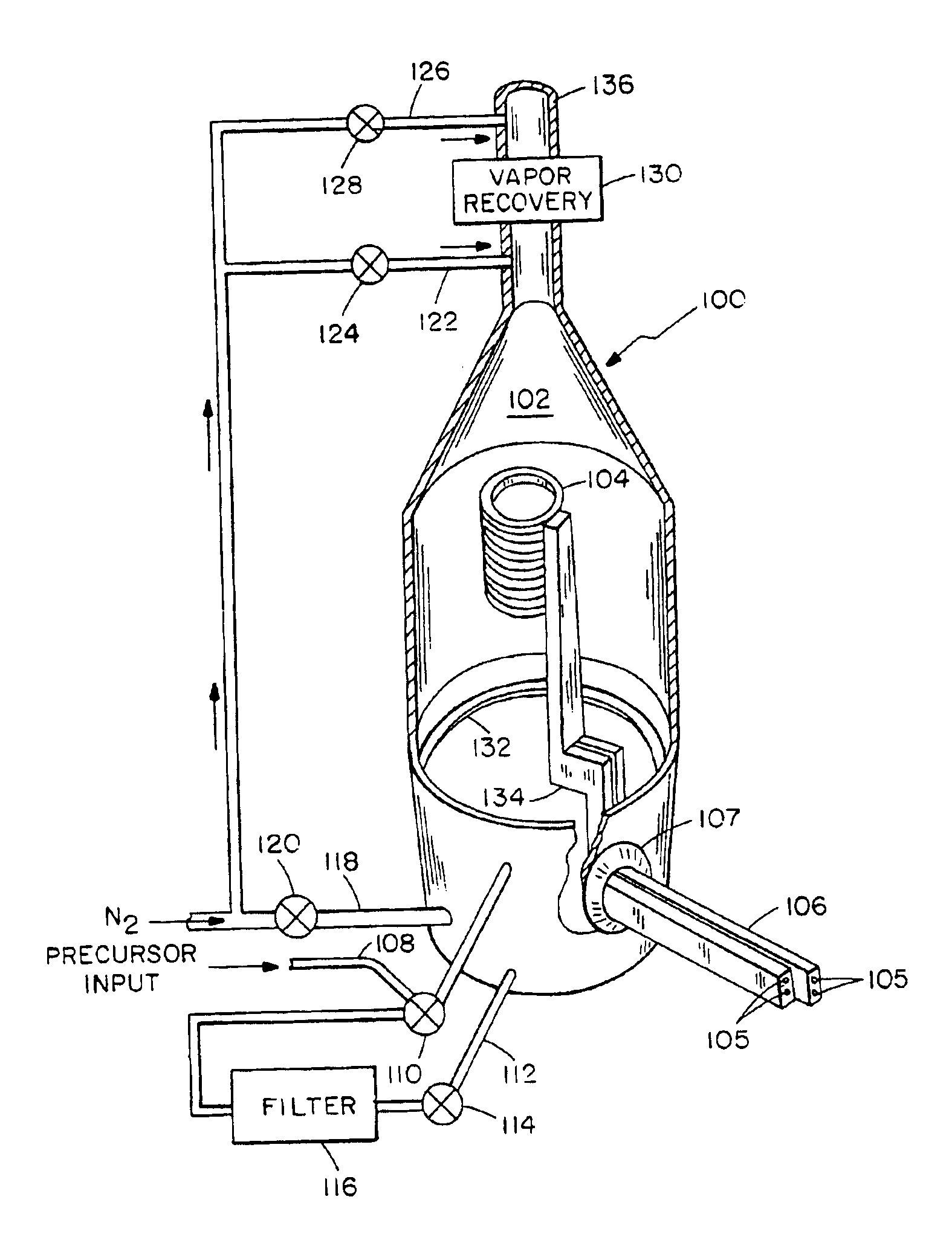
In a method of this invention, a densified composite foam is formed by depositing a coating on an open-cell reticulated foam skeleton.

In one embodiment of the method, the foam skeleton comprises carbon in the form of an open lattice of ligaments, wherein the interconnected pores defined by the lattice have diameters of about 0.5 to about 1.0 mm. The lattice has a micrographic porosity of about 100 pores per inch, a bulk density of about 0.04 g / cm3, and a surface area density o...


PUM

PropertyMeasurementUnit
dielectric constantaaaaaaaaaa
diameteraaaaaaaaaa
densityaaaaaaaaaa

Abstract

A composite structure is formed by depositing a one or more coatings on an open-cell foam skeleton to form a higher-density composite foam. In accordance with one aspect of the invention, the composite foam can be a carbon/carbon composite formed by a rapid densification process. The composite structure is suitable for use, for example, as a friction material employed in clutch and brake devices.

Description

BACKGROUND OF THE INVENTIONRelatively-dense carbon / carbon composites have been found to be highly useful in a variety of structural applications. Because of certain characteristics, such as high strength, high stiffness, light weight, high temperature resistance, and advantageous frictional properties, these composites are desirably suited for use, for example, in the aerospace and automotive brake pad industries. They are favored for use in high-end automotive transmissions but high costs have prevented widespread utilization.Dense carbon / carbon composite structures typically include a carbon fiber matrix, wherein the interstices in the fiber matrix are at least partially filled with deposited carbon. The carbon fibers are high in strength, and are typically in the form of a woven or non-woven fabric or mat. In either case, the carbon fibers provide the composite with structural reinforcement.To fill the carbon fabric with additional carbon, the fibers are typically placed in a cha...

Claims


Application Information

Patent Timeline
Patent Type & Authority Patents(United States)
IPC IPC(8): C04B35/83F16D69/02C04B35/52C04B38/06
CPCC04B35/521C04B38/0615F16D69/023C04B35/83C04B38/0051C04B38/0067C04B38/0074Y10T428/30C04B2235/3826C04B2235/3873C04B2235/48C04B2235/483C04B2235/614C04B2235/80F16D2250/0038Y10T428/249981Y10T428/249961Y10T428/249967Y10T428/249988Y10T428/24999
Inventor LOSZEWSKI, RAYMOND C.
Owner SAFRAN LANDING SYSTEMS
Why Eureka
Try Eureka