Separator for fuel cell and fuel cell

a fuel cell and separator technology, applied in the direction of cell components, cell component details, electrochemical generators, etc., can solve the problems of high contact resistance, subsequent reduction of generated voltage, warp in separator after molding process, etc., to simplify the assembling process, improve gas sealing properties, and stabilize power generation performance

Inactive Publication Date: 2005-02-22
HONDA MOTOR CO LTD
View PDF6 Cites 11 Cited by
  • Summary
  • Abstract
  • Description
  • Claims
  • Application Information

AI Technical Summary

Benefits of technology

Therefore, an object of the present invention is to provide a separator for a fuel cell and a fuel cell in which a warp resulting from press forming is reduced so that it becomes possible to stabilize the power generating performance, to simplify the assembling process and also to improve gas sealing properties.
According to the invention, the rib formed on the circumferential portion makes it possible to increase the rigidity of the circumferential portion, and consequently to make the inner stress, which generates a warp, difficult to be transmitted, thereby preventing the generation of the warp. Therefore, the separator in the present invention has a flat shape as a whole, and when a fuel cell stack is formed by stacking a plurality of membrane electrode assemblies while interpolating the separator therebetween, the surface pressure of the protruding portions contacting the membrane electrode assemblies can be uniform and the contact resistance is reduced, thereby making it possible to stabilize the power generating performance. Moreover, during assembling the fuel cell, it is not necessary to correct the warp in the separator, whereby the assembling operation can be easy and gas sealing properties can be improved. Furthermore, since the rib is located between the current collector unit and the external unit, an air layer inside the rib can improve heat-insulating properties with respect to the external unit. Therefore, the temperature distribution in the current collector unit can be uniform, and the power generating performance can be stabilized.
The rib formed on the circumferential portion of the separator of the present invention is preferably formed in an endless shape along the entire circumference of the circumferential portion. According to this arrangement, it becomes possible to suppress the transmission of the inner stress in any cross-sectional direction, and to prevent a problem in which an area without the rib tends to be warped. In this case, the number of the ribs is at least one, and a plurality of them may be formed, if necessary.

Problems solved by technology

A stress resulting from the press forming tends to occur inside thereof, resulting in a warp in the separator after the molding process.
The separator having a warp causes problems in which the protruding portions are not allowed to contact the gas diffusion electrode plates with a sufficient surface pressure or in which the surface pressure becomes nonuniform, resulting in high contact resistance and a subsequent reduction in generated voltage.
When the fuel cell stack is formed by stacking a plurality of the membrane electrode assemblies while interpolating the separators therebetween, the assembling process has to be carried out while correcting the warp; therefore, the operation is complicated and difficult, resulting in another problem of a reduction in gas sealing properties.

Method used


Image

  • Separator for fuel cell and fuel cell
  • Separator for fuel cell and fuel cell
  • Separator for fuel cell and fuel cell

Examples


examples

Next, an explanation will be given of examples of the present invention.

(1) Preparation of a Separator

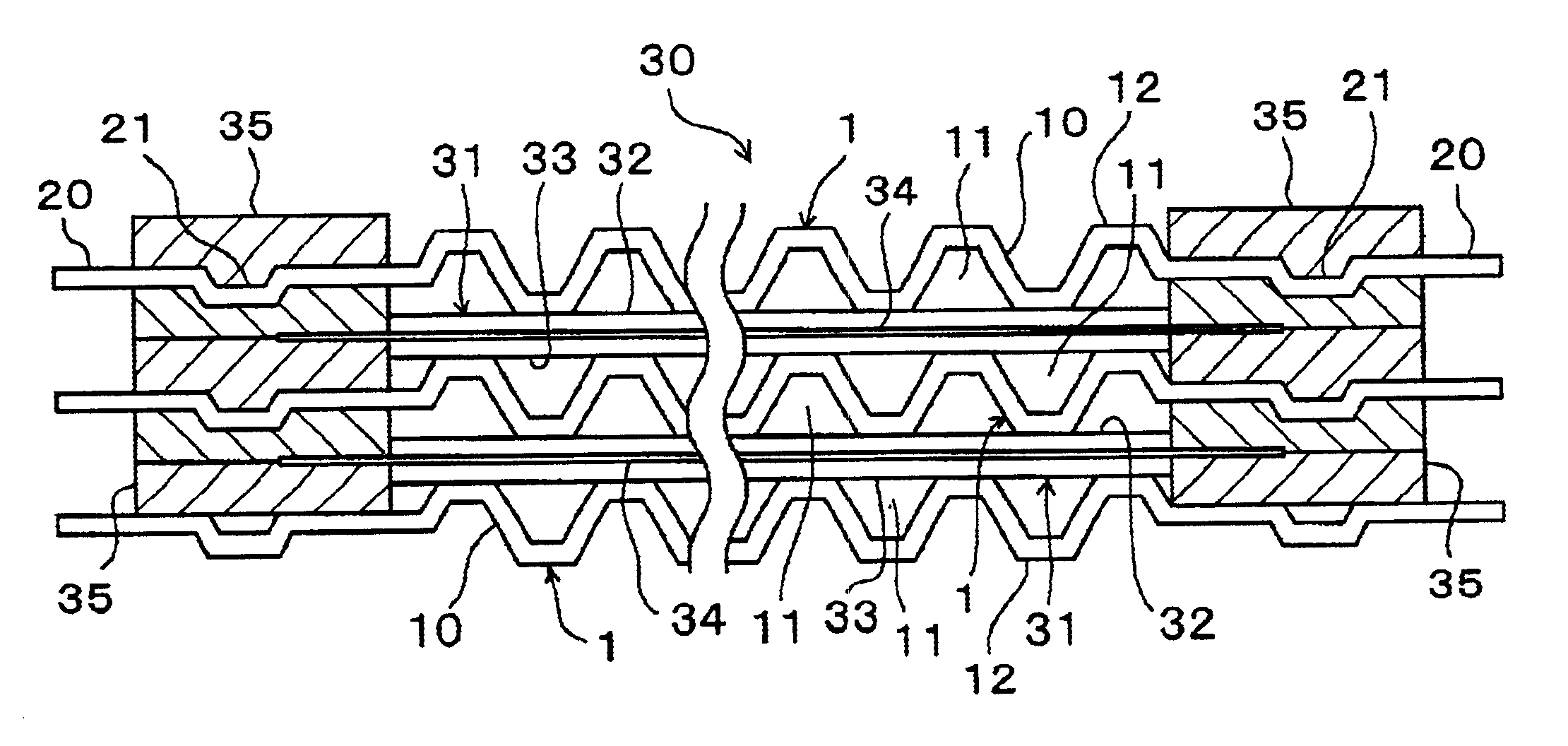
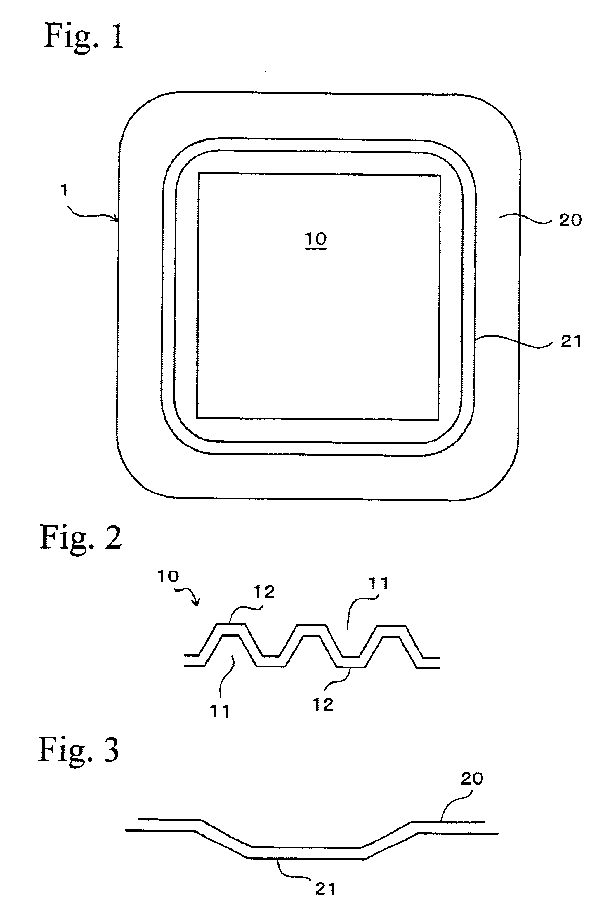
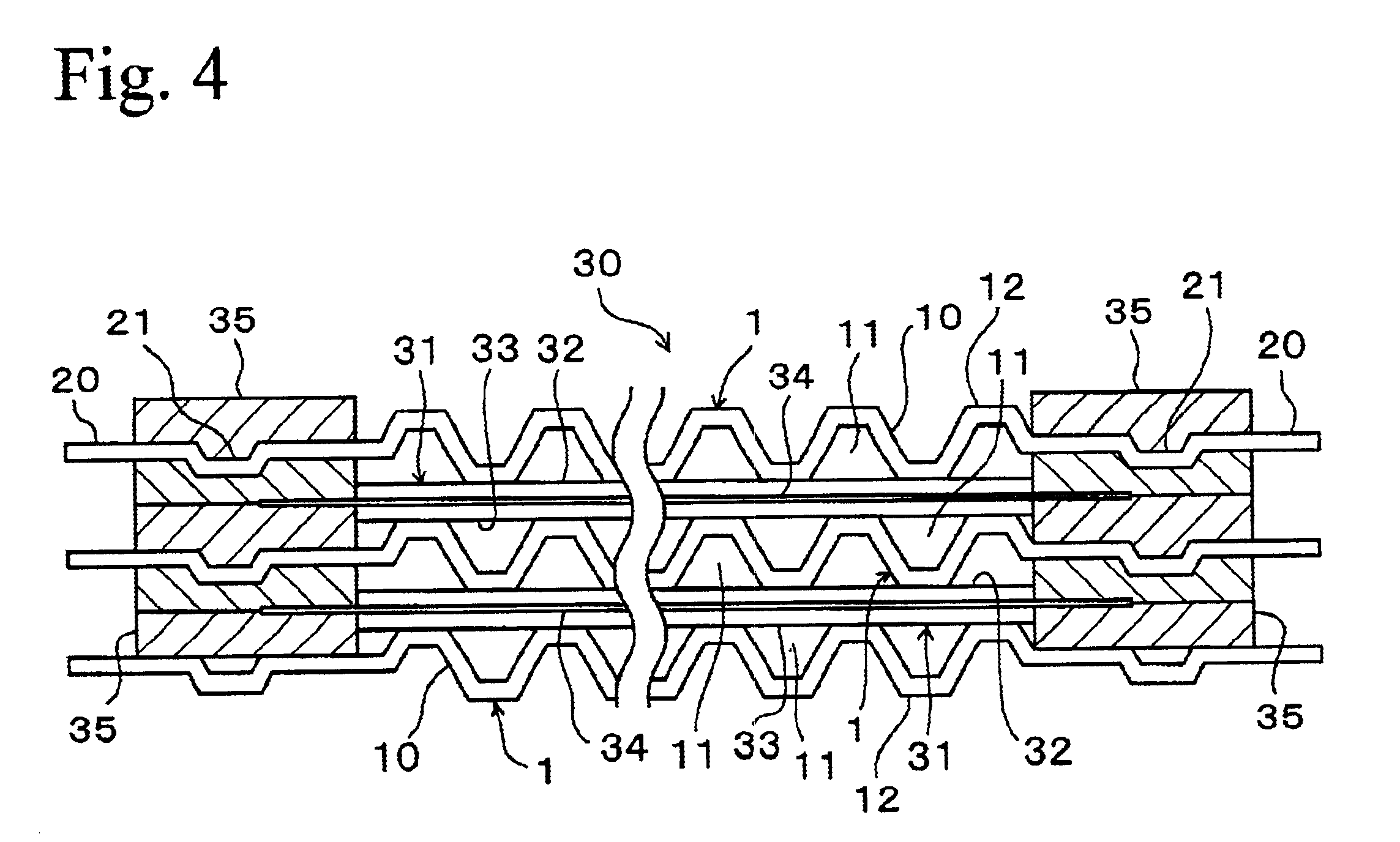
Separators of examples with varied combinations of the width and depth of the rib as shown in Table 1 were obtained by press forming thin plates made of stainless steel in a regular square shape having 86 mm in one side and 0.2 mm in thickness. These separators were formed in the same manner as shown in FIG. 1, and the current collector unit had 60 mm in one side, 1.5 mm in the width of the gas passage and 1.0 mm in the depth of the gas passage, and a rib was formed on a portion extending 2.0 mm from the edge of the current collector unit in a regular square shape along the entire circumference of the circumferential portion. Moreover, a separator was also formed in the same manner as examples except that no rib was formed, as a comparative example.

TABLE 1Amount of warp in separators (unit mm)Depth of rib (mm)Width of rib (mm)0.10.20.30.40.50.50.980.960.950.930.910.80.560.520.490.46...


PUM

PropertyMeasurementUnit
widthaaaaaaaaaa
lengthaaaaaaaaaa
widthaaaaaaaaaa

Abstract

A fuel-cell-use separator is provided with a current collector unit having an irregular shape in its cross-section in which grooved gas passages and / or cooling medium passages and protruding portions contacting a membrane electrode assembly are alternately formed continuously, and a circumferential portion formed on the periphery of the current collector unit, the current collector unit and the circumferential portion being formed by press forming a sheet of metal plate, and in this arrangement, a rib is formed on the circumferential portion.

Description

BACKGROUND OF THE INVENTION1. Technical FieldThe present invention relates to separators constituting a polymer electrolyte fuel cell and relates to a fuel cell using such separators.2. Related ArtIn a polymer electrolyte fuel cell, a separator is layered on both sides of a plate-shaped membrane electrode assembly to form a unit of the layered structure, and a plurality of the units are layered to form a fuel cell stack. The membrane electrode assembly has a three-layered structure, in which an electrolytic membrane made from a resin such as ion-exchange resin is interpolated between a pair of gas diffusion electrode plates (positive electrode plate and negative electrode plate). The separator is stacked in a manner so as to contact the gas diffusion electrode plates of the membrane electrode assembly with gas passages for flowing a gas and cooling medium passages being formed between it and the gas diffusion electrode plate. According to this fuel cell, for example, hydrogen gas as...

Claims


Application Information

Patent Timeline
Patent Type & Authority Patents(United States)
IPC IPC(8): H01M8/02H01M8/10
CPCH01M8/0206H01M8/0247H01M8/0267H01M8/0254Y02E60/50H01M8/026H01M8/241H01M8/0258H01M8/0273
Inventor UTSUNOMIYA, MASAOOHTANI, TERUYUKITSUJI, MAKOTO
Owner HONDA MOTOR CO LTD
Why Eureka
Try Eureka