Continuous slurry polymerization volatile removal

Inactive Publication Date: 2005-02-22
EXXONMOBIL CHEM PAT INC
97 Cites 28 Cited by

AI-Extracted Technical Summary

Problems solved by technology

The cost of compression equipment and the utilities required for its operation often amounts to a significant portion of the expense involved in pr...

Method used

A development which would increases efficiency of the two-stage flash system is the continuous flash line heater. The heater would vaporize up to 100% of the diluent discharged from the reactor with the polymer which would allow greater recovery of the diluent by the intermediate pressure condenser. Diluent recovery through the first flash tank would reduce utility and capital cost. Conventional low pressure single-stage diluent recovery systems include compression, distillation and treatment which have high capital and operating cost. The flash line heater would increase the temperature of the polymer in the downstream dryer system and would create the potential for lower volatile levels in the final product, which would lower variable cost, improves safety and aids attainment of environmental standards.
In a loop reactor, it is not always possible to locate the continuous discharge line in an optimal location to take advantage of centrifugal force to increase the weight percent solids and therefore reduce the amount of isobutane entrained with the polymer solids. It has been observed that a specifically designed pipe as illustrated in FIG. 3 inserted into the loop reactor can increase weight percent solids removed from the reactor. This pipe insert will function in any section of the loop reactor and in a straight section will increase the weight percent solids to that equal to that in a location which takes advantage of centrifugal force to concentrate solids.
It has been observed that by increasing the head and flow capability of the loop reactor circulating pump(s), higher weight percent solids can be circulated in the reactor. It has also been observed that attaining the necessary head and flow from one pump is increasingly difficult as percent solids are increased above 45 weight percent and/or reactor length is increased. Therefore, the use of two pumps in series allows a doubling of pumping head capability and a resulting percent solids increase. Increased weight percent solids in the loop reactor increases catalyst residence time, which for chrome oxide and Ziegler-Natta catalysts, increases catalyst productivity. One can choose to take advantage of higher percent solids and longer residence time by keeping production rate constant at reduced catalyst feed rate and improve the catalyst yield. Another alternative is to maintain catalyst feed rate constant and increase the reactor throughput and therefor increase STY at nearly constant catalyst productivity. Higher solids also increases the weight percent solids removed from the reactor which reduces isobutane processing cost in recycle equipment. Desirably, the higher solids are removed continuously. Continuous discharge may occur through a single point discharge line.
It is desirable to control the amount of vapor condensed in the heat exchanger 23E and to maintain sufficient vapor pressure in the accumulator 24B. In this way, a pressure control valve 24A can maintain sufficient back pressure on the accumulator 24B. By maintaining a sufficient back pressure on the accumulator 24B, a proper operating pressure is maintained in the first flash tank 11. The pressure control valve 24A is actuated by a pressure indicating controller 24C in concert with a pressure element 24D. The pressure element 24D is in sensing communication with the accumulator 24B. The pressure element 24D generates an signal proportional to the pressure in the accumulator 24B. In response to this signal and a preset pressure value, the pressure indicating controller 24C sends a signal through a signal conduit (illustrated by the broken line 24E) to the control valve 24A which selectively controls the back pressure on the accumulator 24B.
Referring back to the first flash tank 11, the concentrated polymer solids/slurry in the bottom of the first flash tank 11 continuously settles by sliding along the straight line bottom surface 16 thereof into the seal chamber 17 which is illustrated in enlargement FIG. 2. A polymer solids/slurry level 43 is maintained in the seal chamber 17 to eliminate plugging tendencies in first flash tank 11 and to form a pressure seal so that the first flash tank 11 can operate at a substantially higher pressure than the second flash tank 15. Polymer slurry/solids are continuously discharged from the seal chamber 17 into the lower pressure second flash tank 15. The length (l), diameter (d), and volume of the seal chamber 17 and the geometry of the seal chamber exit reducer 18 are chosen so as to provide a variable residence time and provide a continuous plug flow of concentrated polymer solids/slurry to minimize “dead” space and reduce plugging tendencies. The seal chamber 17 length must be sufficient to allow particle (polymer solids) level measurement and control.
Referring now to the cyclone 13, the major portion of the liquid medium in the polymeri...

Benefits of technology

The claimed apparatus and process provide several advantages over the prior art including: (1) allowing for a continuous processing of the contents of a slurry reactor from the point of discharge of the polymerization slurry effluent through a discharge valve; a first flash tank; a seal chamber; a seal chamber exit reducer; and therefrom to a second flash tank, (2) significantly increasing ethylene concentration in t...

Abstract

A process/apparatus is disclosed for continuously separating a liquid medium comprising diluent and unreacted monomers from a polymerization effluent comprising diluent, unreacted monomers and polymer solids, comprising a continuous discharge of the polymerization effluent from a slurry reactor through a discharge valve and transfer conduit into a first intermediate pressure flash tank with a conical bottom defined by substantially straight sides inclined at an angle to that of horizontal equal to or greater than the angle of slide of the slurry/polymer solids and an exit seal chamber of such diameter (d) and length (l) as to maintain a desired volume of concentrated polymer solids/slurry in the exit seal chamber such as to form a pressure seal while continuously discharging a plug flow of concentrated polymer solids/slurry bottom product of said first flash tank from the exit seal chamber through a seal chamber exit reducer with inclined sides defined by substantially straight sides inclined at an angle to that of horizontal equal to or greater than the angle of slide of the polymer solids which remain after removal of about 50 to 100% of the inert diluent therefrom to a second flash tank at a lower pressure.

Application Domain

Technology Topic

DiluentMonomer +7

Image

  • Continuous slurry polymerization volatile removal
  • Continuous slurry polymerization volatile removal
  • Continuous slurry polymerization volatile removal

Examples

  • Experimental program(4)

Example

Example 1
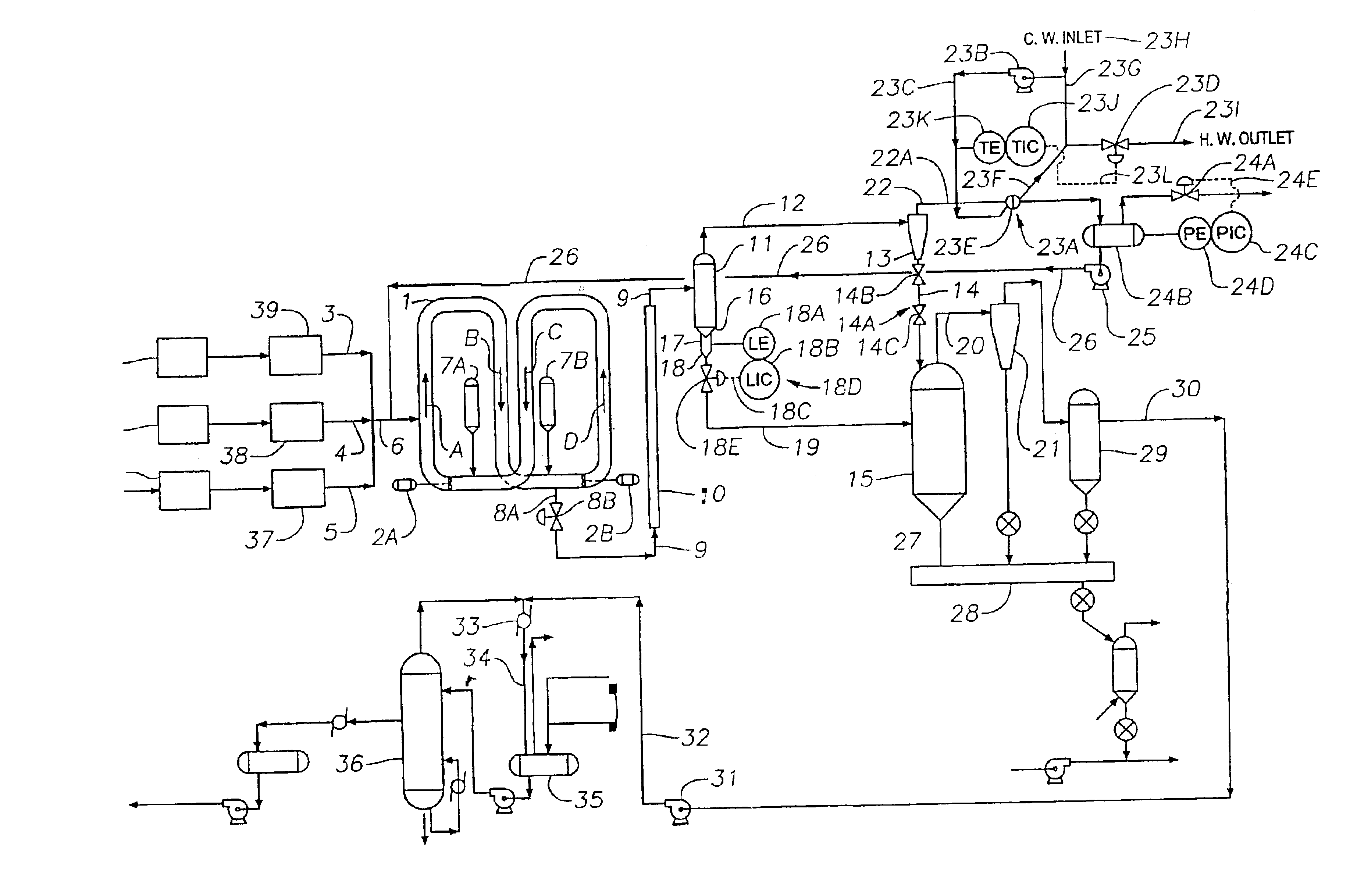
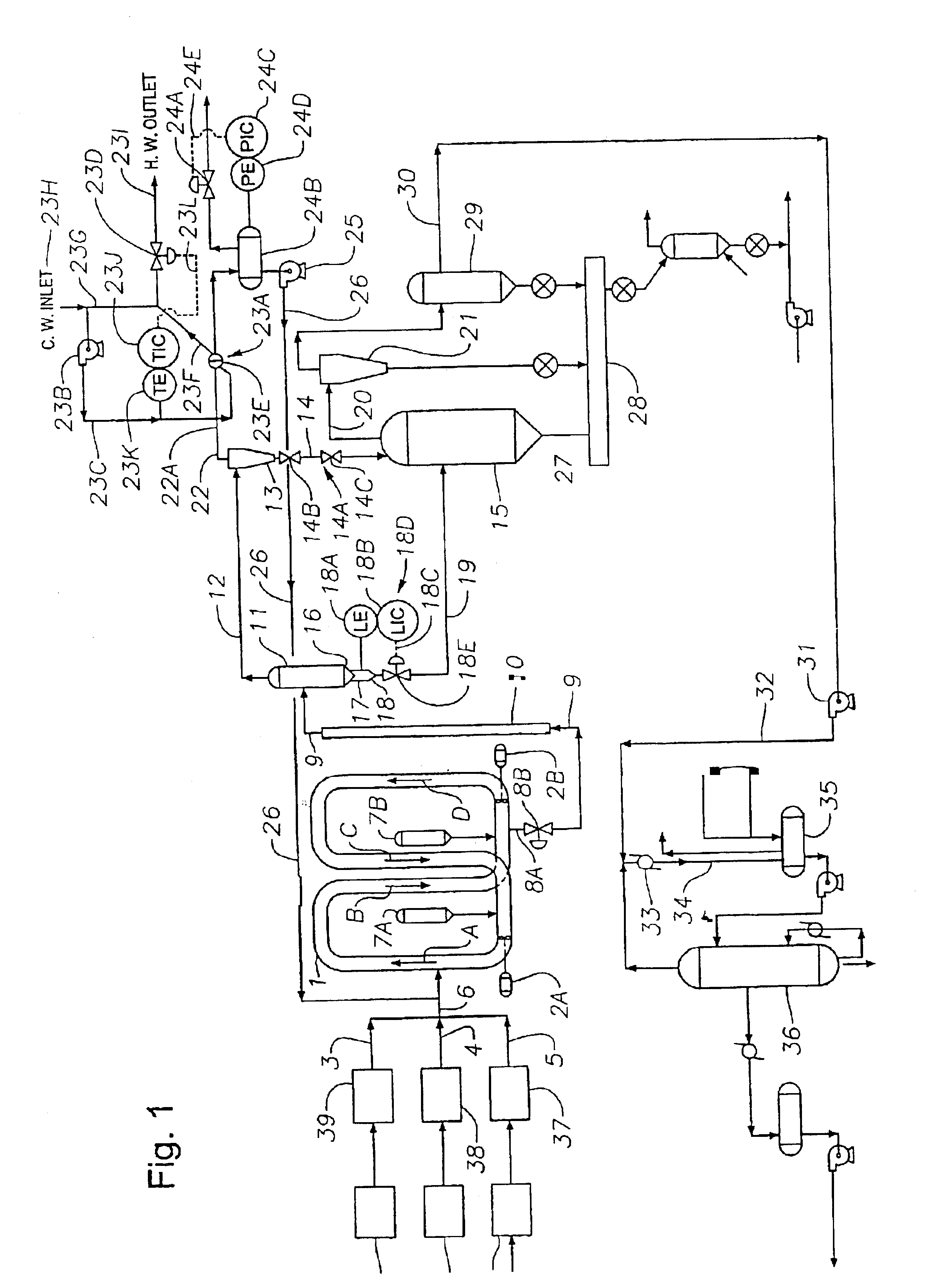
A typical ethylene polymerization process can be conducted at a temperature of about 215° F. and a pressure of 565 psia. An example of such a process would result in a polymerization effluent of about 83,000 pounds per hour comprising about 45,000 pounds per hour of polyethylene polymer solids and about 38,000 pounds per hour of isobutane and unreacted monomers. The continuously discharged polymerization effluent is flashed in the first flash tank at a pressure of about 240 psia and a temperature of about 180° F. to remove overhead about 35,000 pounds per hour of diluent and unreacted monomer vapors and entrained particulates. Auxiliary heat to impart an additional quantity of heat to the polymerization effluent is supplied by appropriate heating means during the transit between the discharge valve and the first flash tank. After removal of the fines, the isobutane vapor is condensed, without compression, by heat exchange at a pressure of about 240 psia and a temperature of about 135° F. The polymer slurry/solids discharging from the bottom of the first flash tank into the seal chamber form a continuous plug flow of concentrated polymer slurry/solids, which provides a pressure seal, with an l/d ratio of the plug of polymer slurry/solids of 2.5 in an 8′4″ long seal chamber having an l/d ratio of 5.5 and with a cone angle of about 68° on the seal chamber exit reducer. The residence time of the continuous plug flow of concentrated polymer slurry/solids is about 16 seconds. The concentrated polymer slurry/solids are continuously discharged from the bottom of the first flash tank at a temperature of about 180° F. and a pressure of about 240 psia through a seal chamber, seal chamber exit reducer, and a second transfer conduit into a feed inlet on a second flash tank. The remaining liquid medium in the concentrated polymer slurry/solids communicated to the second flash tank is flashed at a temperature of about 175° F. and at a pressure of about 25 psia to remove about 4,300 pounds per hour of isobutane and unreacted monomers which are condensed by compression and heat exchange.

Example

Example 2
A typical ethylene polymerization process can additionally be conducted at a temperature of about 215° F. and a pressure of 565 psia. An example of such a process would result in a polymerization effluent of about 83,000 pounds per hour comprising about 45,000 pounds per hour of polyethylene polymer solids and about 38,000 pounds per hour of isobutane and unreacted monomers. The continuously discharged polymerization effluent is flashed in the first flash tank at a pressure of about 240 psia and a temperature of about 175° F. to remove overhead about 23,000 pounds per hour of diluent and unreacted monomer vapors and entrained particulates. After removal of the fines, the isobutane vapor is condensed, without compression, by heat exchange at a pressure of about 240 psia and a temperature of about 112° F. The polymer slurry/solids discharging from the bottom of the first flash tank into the seal chamber form a continuous plug flow of concentrated polymer slurry/solids, which provides a pressure seal, with an l/d ratio of the plug of polymer slurry/solids of 2.5 in an 8′4″ long seal chamber with an l/d ratio of 5.5 and with a cone angle of about 68° on the seal chamber exit reducer. The residence time of the continuous plug flow of concentrated polymer slurry/solids in the seal chamber is about 16 seconds. About 60,000 pounds per hour of concentrated polymer slurry/solids are continuously discharged from the bottom of the first flash tank at a temperature of about 175° F. and a pressure of about 240 psia through a seal chamber, seal chamber exit reducer and a second transfer conduit into a feed inlet on a second flash tank. The remaining liquid medium in the concentrated polymer slurry/solids communicated to the second flash tank is flashed at a temperature of about 125° F. and at a pressure of about 25 psia to remove about 16,000 pounds per hour of isobutane and unreacted monomer which are condensed by compression and heat exchange.

Example

Example 3
An example of a typical ethylene polymerization process was carried out in an eight leg, 20 inch reactor with settling legs having an overall length of 833 ft and a volume of 11,500 gallons. The reactor was equipped with a single flash tank (requiring 100% compression of all diluent discharged from the reactor), a single 460-480 kilowatt circulating pump having a pump head in the range from 85 ft to 110 ft, producing a circulation rate in the range from 21,000 to 28,000 gallons per minute (gpm) and operated in a discontinuous discharge mode. The polymerization temperature and pressure in the reactor would be between about 215° F. to 218° F. and a pressure of 565 psia.
In the process of example 3, the reactor slurry density is in the range from 0.555 gm/cc to 0.565 gm/cc, a polymer production rate range from 28,000 pounds to 31,000 pounds per hour while maintaining a reactor solids concentration weight percentage in the range from 46 to 48 with a polymer residence time in the range from 0.83 to 0.92 hours. Space time yield (STY) was in the range from 2.4 to 2.7. Example 3 data and results are further illustrated in Table 1.

PUM

PropertyMeasurementUnit
Fraction0.5 ~ 1.0fraction
Weight
Pressure
tensileMPa
Particle sizePa
strength10

Description & Claims & Application Information

We can also present the details of the Description, Claims and Application information to help users get a comprehensive understanding of the technical details of the patent, such as background art, summary of invention, brief description of drawings, description of embodiments, and other original content. On the other hand, users can also determine the specific scope of protection of the technology through the list of claims; as well as understand the changes in the life cycle of the technology with the presentation of the patent timeline. Login to view more.

Similar technology patents

High grade non- oriented silicon steel and method for manufacturing same

ActiveCN101333620AReduce furnace roll nodulesReduce energy consumptionTemperature control deviceSheet steelElectrical steel
Owner:BAOSHAN IRON & STEEL CO LTD

Classification and recommendation of technical efficacy words

Why Eureka
Try Eureka