Sweeping real-time single point fiber

a fiber and real-time technology, applied in the field of medical imaging arts, can solve the problems of wasting reconstruction time, inability to discern fibrous structure information from dt-mri images, and inability to easily discern fiber structures in conventional mri, so as to achieve more meaningful images and improve computational speed

Inactive Publication Date: 2005-02-22
KONINKLIJKE PHILIPS ELECTRONICS NV
View PDF11 Cites 32 Cited by
  • Summary
  • Abstract
  • Description
  • Claims
  • Application Information

AI Technical Summary

Benefits of technology

One advantage of the present invention resides in substantially real time structure realization.
Another advantage of the present invention resides in improved computational speed.
Yet another advantage of the present invention resides in more meaningful images.
Numerous additional advantages and benefits of the present invention will become apparent to those of ordinary skill in the art upon reading the following detailed description of the preferred embodiment.

Problems solved by technology

The fiber structures are typically not easily discernable in conventional MRI images.
Extraction of fibrous structure information from DT-MRI images is computationally intensive.
In cases where the data is not useful, reconstruction times are wasted.

Method used


Image

  • Sweeping real-time single point fiber
  • Sweeping real-time single point fiber
  • Sweeping real-time single point fiber

Examples


Embodiment Construction

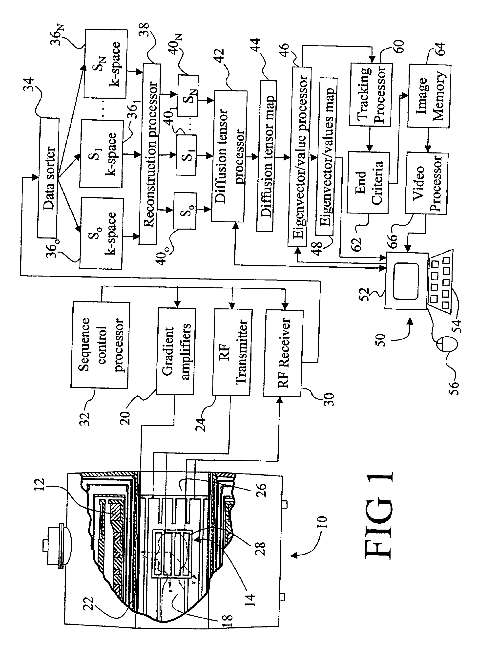
With reference to FIG. 1, a magnetic resonance imaging (MRI) scanner 10 typically includes superconducting or resistive magnets 12 that create a substantially uniform, temporally constant main magnetic field B0 along a z-axis through an examination region 14. Although a bore-type magnet is illustrated in FIG. 1, the present invention is also applicable to open magnet systems and other types of MRI scanners. Imaging is conducted by executing a magnetic resonance excitation and readout sequence with the subject being imaged, e.g. a patient 18, placed at least partially within the examination region 14, typically with the region of interest at an isocenter of the magnet 12. For diffusion tensor MRI imaging of the brain region, the patient's head is preferably placed at the isocenter.

The magnetic resonance sequence includes a series of RF and magnetic field gradient pulses that are applied to the subject 16 to manipulate and detect magnetic resonance. More specifically, gradient pulse a...


PUM

PropertyMeasurementUnit
diffusion imagingaaaaaaaaaa
thresholdaaaaaaaaaa
angleaaaaaaaaaa

Abstract

An imaging method for imaging a subject (18) including fibrous/anisotropic structures (102) includes acquiring three-dimensional image representations without and with a plurality of different diffusion weighting and directions. When a user (56) hovers a selection device over a voxel of the image, a fiber representation (54) is extracted in substantially real time. The representation is generated by following a direction of a major eigenvector e1 from voxel to voxel. A human-viewable display of the fiber representation is produced (210).

Description

BACKGROUND OF THE INVENTIONThe present invention relates to medical imaging arts. In particular, it relates to the imaging, tracking, and displaying of neural fibers and fiber bundles by diffusion tensor magnetic resonance imaging (DT-MRI), and will be described with particular reference thereto. However, the invention will also find application in conjunction with tracking and graphical rendering of other types of fibrous structures, as well as with other imaging modalities.Nerve tissue in human beings and other mammals includes neurons with elongated axonal portions arranged to form neural fibers or fiber bundles along which electrochemical signals are transmitted. In the brain, for example, functional areas defined by very high neural densities are typically linked by structurally complex neural networks of axonal fiber bundles. The axonal fiber bundles and other fibrous material are substantially surrounded by other tissue.Diagnosis of neural diseases, planning for brain surgery...

Claims


Application Information

Patent Timeline
Patent Type & Authority Patents(United States)
IPC IPC(8): G01R33/563G01R33/54G06T5/00G06T17/00G01R33/56A61B5/055G01N24/08G06T15/08
CPCG01R33/56341G06T5/50G06T15/08G06T2207/30016G06T2207/10092G06T2207/20221
Inventor VAN MUISWINKEL, ARIANNE M. C.HOLTHUIZEN, RONALDUS F. J.
Owner KONINKLIJKE PHILIPS ELECTRONICS NV
Why Eureka
Try Eureka