Method of programmed displacement for prolong usage of optical elements under the irradiation of intensive laser beams

a laser beam and optical element technology, applied in laser surgery, mountings, instruments, etc., can solve the problems of laser induced damage on the surface or inside of optical elements, crystal or optical elements may degrade with time, laser induced damage in optical elements, etc., to prolong the usage life of uv crystals, stable uv generation, and eliminate motion-induced power fluctuation

Inactive Publication Date: 2005-02-22
VOLTERRA SEMICONDUCTOR
View PDF8 Cites 48 Cited by
  • Summary
  • Abstract
  • Description
  • Claims
  • Application Information

AI Technical Summary

Benefits of technology

The present invention contemplates a programmed displacement of the UV crystal to solve the above-identified problems. The present invention contemplates to make the crystal displacement in a programmable fashion controlled by a microprocessor. The crystal is first scanned to map all defect locations and these defect locations are recorded in the microprocessor memory. The crystal is then displaced step by step over the non-defect area. At each step location, the crystal stays stationary for a predetermined period of time to eliminate motion-induced power fluctuation of UV generation. The predetermined period of time is much shorter than the degradation time of the crystal at the given irradia

Problems solved by technology

When a nonlinear optical crystal or any optical element is irradiated with an intensive laser beam, the performance of the crystal or optical element may degrade with time.
Laser induced damage may happen on the surface of or inside an optical element.
There are many mechanisms leading to laser induced damage in optical element.
Some mechanisms lead to instance damages, while some other mechanisms lead to degradation over time in the early stage before a complete damage.
For high intensity UV generation in BBO, for example, color center or other defects may be induced and accumulated in an early stage before a sudden damage happen.
One problem stemming from a continuous motion is a possible fluctuation in the generated UV beam, due to i

Method used


Image

  • Method of programmed displacement for prolong usage of optical elements under the irradiation of intensive laser beams
  • Method of programmed displacement for prolong usage of optical elements under the irradiation of intensive laser beams
  • Method of programmed displacement for prolong usage of optical elements under the irradiation of intensive laser beams

Examples


Embodiment Construction

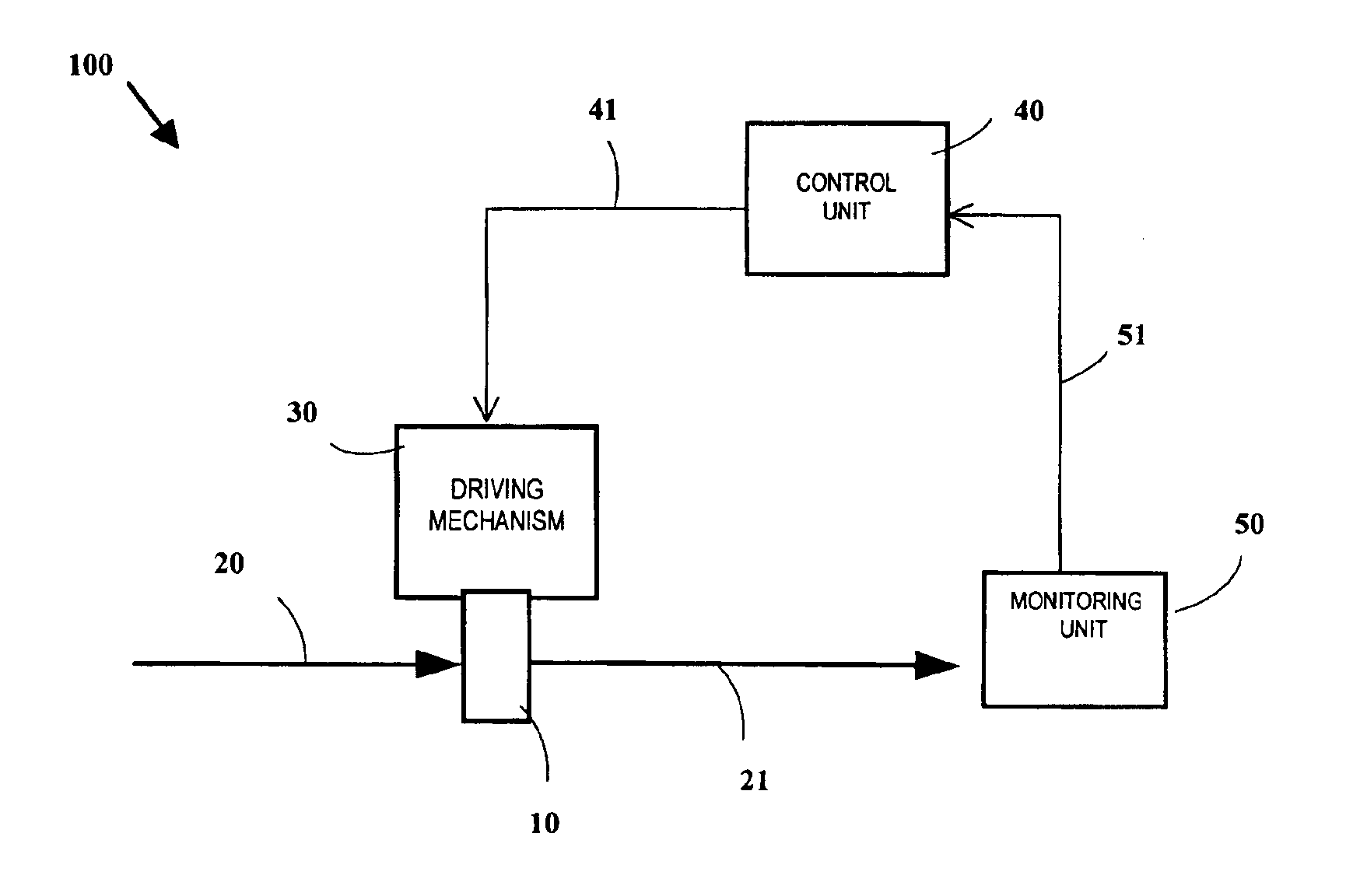
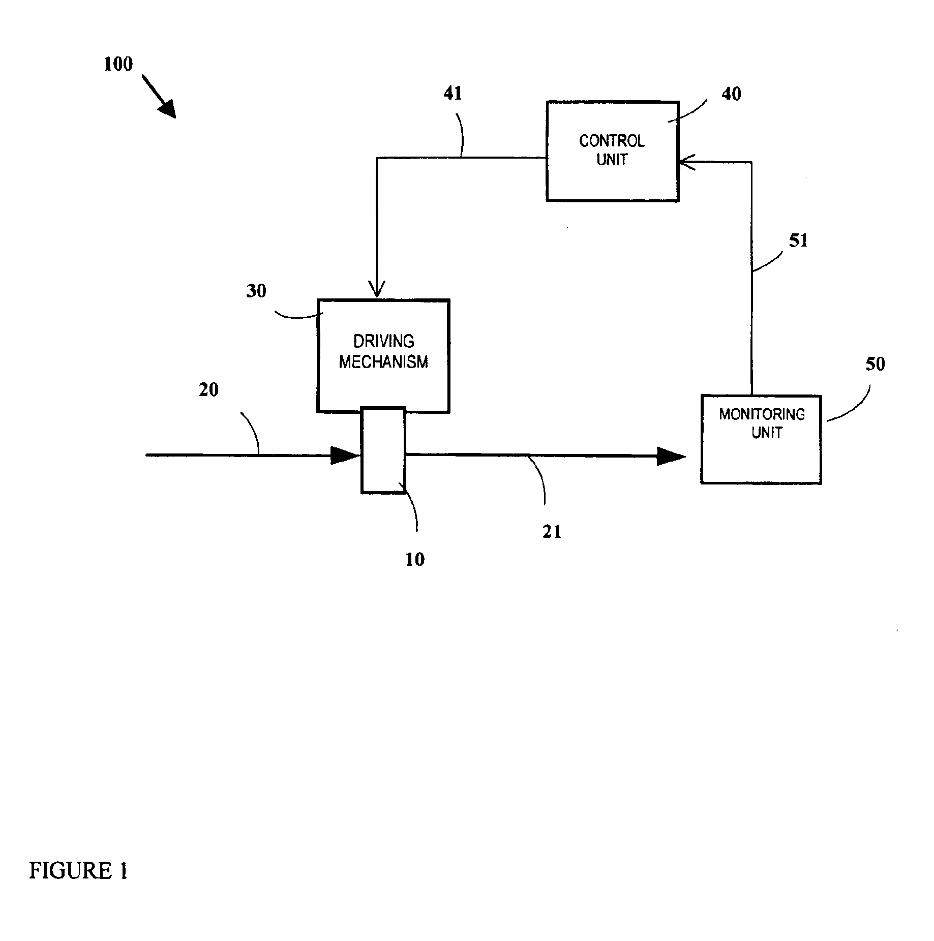
FIG. 1 is a block diagram 100 showing a design concept of programmed displacement for prolonging usage of an optical element 10 under the irradiation of an intensive laser beam 20, in accordance with the present invention. The block diagram 100 includes an optical element 10, an intensive laser beam 20, a transmitted or output laser beam 21, a driving mechanism 30, a control unit 40, and a monitoring unit 50.

The optical element 10 can be a piece of UV optics, a laser crystal, or a nonlinear optical crystal. Examples of laser crystal include Nd:YLF, Cr:LiSAF, Cr:YAG, and Ho:YAG. Examples of nonlinear optical crystals include BBO, LBO, CLBO, KTP, KD*P, and KDP crystals.

The intensive laser beam 20 can be a CW or pulsed laser beam with predetermined spot size, wavelength, and power density. The wavelength of the intensive laser beam 20 can be in the range from 100 nm to 1 micron. For a pulsed laser beam, the intensive laser beam 20 can have pulse duration in the range of 1 fs to 10 ms.

T...


PUM


Abstract

The present invention contemplates a programmed displacement to prolong the usage life of UV crystal for deep UV generation by displacing step by step the crystal with interval between steps much shorter than the degradation time of the crystal. Meanwhile, the present invention contemplates the programmed displacement to obtain stable UV generation by avoiding defect locations of the crystal. Further, the present invention contemplates the programmed displacement to achieve optimal stability in UV power for each layer of UV ablation in photo-refractive surgery.

Description

TECHNICAL FIELDThe present invention relates to a device and method for prolonging the usage life of an optical element under the irradiation of an intensive laser beam by programmed displacement of the optical element. In particularly, the present invention relates to a delay or complete elimination of laser beam damage on nonlinear optical crystals, such as BBO, LBO, CLBO, KTP, KD*P, and KDP.BACKGROUNDWhen a nonlinear optical crystal or any optical element is irradiated with an intensive laser beam, the performance of the crystal or optical element may degrade with time. The higher the incident laser beam intensity, the faster it degrades. This degradation process is usually referred to as laser induced damage. Laser induced damage may happen on the surface of or inside an optical element.There are many mechanisms leading to laser induced damage in optical element. Some mechanisms lead to instance damages, while some other mechanisms lead to degradation over time in the early stag...

Claims


Application Information

Patent Timeline
IPC IPC(8): G02F1/35G02B7/00A61F9/01A61F9/007G02B26/00
CPCG02B26/00G02F1/3525A61F9/008A61F9/00802G02B7/005A61F9/00821A61F2009/00842A61F2009/00872A61F2009/00897
Inventor LAI, MINGQU, ZHIMINMOHEBI, MEHRDAD
Owner VOLTERRA SEMICONDUCTOR
Why Eureka
Try Eureka