Phase-change memory element and method of storing data therein

a phase-change memory and data technology, applied in the field of data storage methods, can solve the problem of low programming energy of amorphous phases

Inactive Publication Date: 2005-02-22
OVONYX MEMORY TECH LLC
View PDF2 Cites 44 Cited by
  • Summary
  • Abstract
  • Description
  • Claims
  • Application Information

AI Technical Summary

Problems solved by technology

In addition, the amorphous phase requires low pro

Method used


Image

  • Phase-change memory element and method of storing data therein
  • Phase-change memory element and method of storing data therein
  • Phase-change memory element and method of storing data therein

Examples


Embodiment Construction

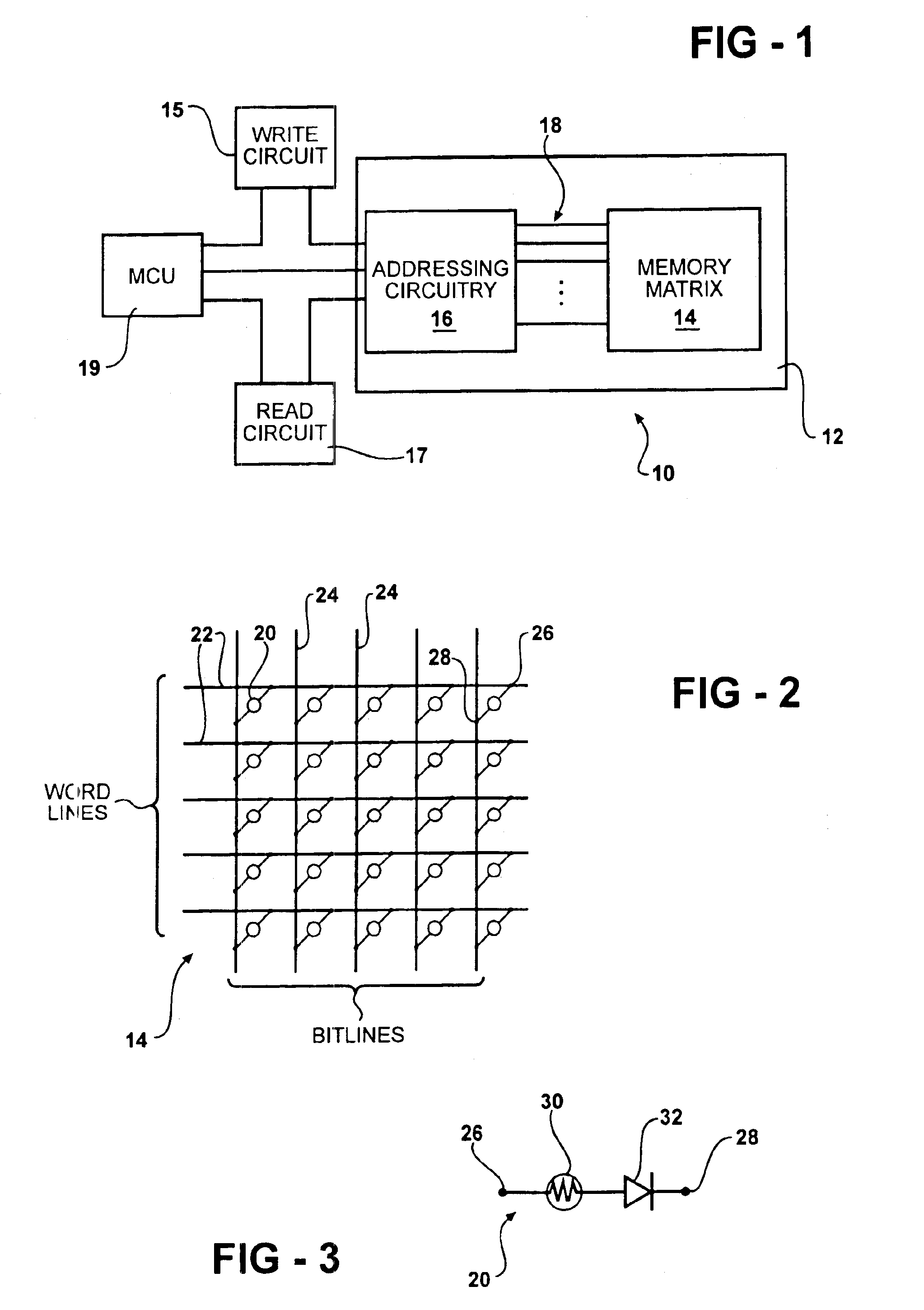
Programmable resistance memory elements comprise a volume of phase-change memory material that is programmable between an amorphous phase and a crystalline phase by application of set and reset pulses as previously described. The pulses can originate from any type of energy source such as particle beam energy, optical energy, thermal energy, electromagnetic energy, acoustical energy, pressure energy, etc. The amorphous phase is a relatively high resistance state, while the crystalline phase is a relatively low resistance state. FIG. 1 shows individual programmable resistance memory elements (shown in FIG. 2) combined into a memory array, or matrix, 14 in a data storage, or memory, device 10. The memory device 10 includes a plurality of memory cells 20 for storing data. The memory matrix 14 is an integrated circuit memory array 14 mounted on a substrate 12 and is coupled to addressing circuitry 16 by the plurality of control lines 18. The addressing circuitry 16 is often fabricated u...


PUM


Abstract

A phase-change memory element including a phase-change material. The phase-change memory element has a plurality of memory state wherein each of the memory states has a corresponding threshold voltage. The threshold voltages may be used to determine the current memory state of the memory element. The phase-change material may include a chalcogen element.

Description

FIELD OF THE INVENTIONThe present invention relates generally to electrically programmable, phase-change memory elements and more particularly to a method for data storage in the phase-change memory elements.BACKGROUND OF THE INVENTIONProgrammable phase-change memory elements formed from materials that can be programmed to exhibit at least two detectably distinct electrical resistivities are known in the art. Phase-change materials may be programmed between a first structural phase where the material is generally more amorphous and a second structural phase where the material is generally more crystalline. The term amorphous as used herein, refers to a condition that is relatively structurally less ordered or more disordered than a single crystal and has a detectable characteristic, such as high electrical resistivity. The term crystalline, as used herein, refers to a condition that is relatively structurally more ordered than amorphous and has lower electrical resistivity than the ...

Claims


Application Information

Patent Timeline
IPC IPC(8): G11C16/02G11C11/34G11C16/10
CPCG11C11/56G11C11/5678G11C13/0004G11C13/0069G11C13/004G11C2013/009G11C2013/0045
Inventor PASHMAKOV, BOIL
Owner OVONYX MEMORY TECH LLC
Why Eureka
Try Eureka