Substrate coating unit and substrate coating method

a substrate coating and coating unit technology, applied in the direction of coatings, liquid surface applicators, movable spraying apparatus, etc., can solve the problems of increasing shearing stress, affecting the application state of resist solution immediately after application, and affecting the flatness of coating solution, so as to reduce the amount of resist solution, and reduce the effect of evaporation of solven

Inactive Publication Date: 2005-03-01
TOKYO ELECTRON LTD
View PDF2 Cites 12 Cited by
  • Summary
  • Abstract
  • Description
  • Claims
  • Application Information

AI Technical Summary

Benefits of technology

As described above, it is feared that when the substrate is moved, the coating solution on the substrate is drawn backward with respect to the direction of movement by a shearing stress due to a velocity gradient of the air current, resulting in the coating solution on the substrate becoming thinner on the movement direction side. In the present invention, however, a wide gap is provided between the substrate and the cover, which restrains a large shearing stress from occurring on the surface of the substrate immediately after the application to thereby restrain the coating solution from becoming thinner only on the movement direction side. Thereby, evenness in thickness of the coating solution is secured within a substrate plane. Further, since the cover is provided at an angle, the gap between the substrate and the cover narrows as the substrate advances in the one direction, so that excessive evaporation of the solvent in the coating solution can be restrained.
Further, if the cover is lowered on the discharge nozzle side, when the substrate immediately after the application is moved in the one direction, a narrow gap is formed between the substrate and the cover. Then, a shear flow formed in the gap by the movement of the substrate causes a shearing stress on the surface of the coating solution, so that the coating solution can be flattened by the shearing stress. Particularly when the coating solution is applied in a manner of so-called drawing with one stroke, a heap of the coating solution is formed along the application path immediately after the application, but the coating solution is flattened by the shear flow, resulting in improved flatness of the coating solution.
The lower face of the aforementioned cover may be curved. By thus curving the lower face of the cover, an air current between the substrate and the cover smoothly flows along the curved face to stable the behavior of the air current. This stables the coating solution which is susceptible to the air current, resulting in the formation of an appropriate coating film on the substrate.
In the present invention, it is also preferable that the cover has a flat plate shape with a uniform thickness and a cover raising and lowering mechanism for raising and lowering a part of the cover is provided. The cover can be raised and lowered by a predetermined distance to be inclined by the cover raising and lowering mechanism. Further, by adjusting the raising and lowering distance, an inclined angle of the cover can be adjusted, so that the distance of the gap between the substrate and the cover becomes adjustable. Therefore, the distance is preferably adjusted based on the film thickness, which makes it possible to restrain the evaporation of the solvent from the coating solution to a minimum while restraining the influence of the air current.
The cover raising and lowering mechanism may be configured to raise and lower portions in vicinities of both ends along the one direction of the cover. By raising and lowering both ends of the cover, the raising and lowering distance of both ends can be adjusted to adjust the inclined angle of the cover. Further, since the whole cover can be moved up and down by raising and lowering both ends of the cover at both sides, the distance of the gap between the substrate and the cover can be changed. By changing the distance of the gap, the air current formed between the substrate and the cover can be controlled. Therefore, it is possible to secure the flatness of the coating solution while restraining the evaporation of the solvent of the coating solution on the substrate by adjusting the distance of the gap in accordance with the type of the coating solution, the film thickness, and the moving speed of the substrate.
According to the coating method of the present invention, when the substrate is shifted in the one direction, the cover is also moved in the same direction, so that the air current formed between the substrate and the cover by the movement of the substrate decreases in velocity gradient. This reduces the influence of the air current exerted upon the coating solution on the substrate, so that the behavior of the coating solution stables to secure the flatness of the coating solution. Further, the cover is moved to its original position while the discharge nozzle is discharging the coating solution onto the substrate, which prevents a large amount of solvent from evaporating due to the cover deviating from a position above the substrate, so that a space for moving the cover is reduced to a minimum.

Problems solved by technology

However, in the spin coating method, the wafer is rotated at a high speed, which causes a large amount of the resist solution to scatter from the peripheral portion of the wafer, resulting in much waste resist solution.
Further, there is a disadvantage that a unit for the coating is contaminated by the scattered resist solution, and thus the unit needs to be cleaned frequently, and so on.
However, the resist solution, if left as it is, heaps up along an application path, and thus the resist solution needs to be diffused over the entire face of the wafer after the application.
Further, since the air current has a velocity gradient due to the influence of the cover and a shearing stress is generated on the wafer surface by the velocity gradient, the application state of the resist solution immediately after the application might be disturbed by the shearing stress.
Furthermore, it is also feared that the shearing stress increases as the cover is brought closer to the wafer to lose the flatness of the resist solution.
If the flatness of the resist solution is lost as described above, a resist film having a uniform film thickness is not formed on the wafer, resulting in a decrease in yield.

Method used


Image

  • Substrate coating unit and substrate coating method
  • Substrate coating unit and substrate coating method
  • Substrate coating unit and substrate coating method

Examples


second embodiment

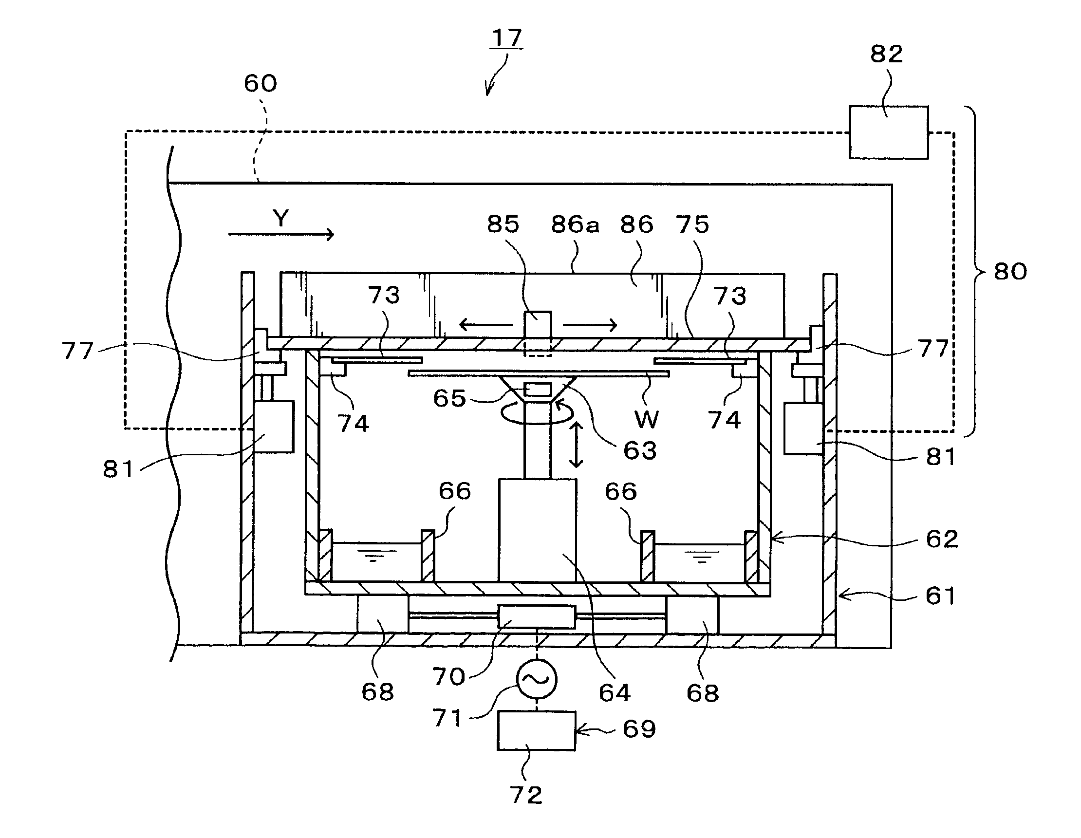
As described above, the gap between the wafer W and the cover 111 is positively narrowed so that the resist solution on the wafer W is evened by the shearing stress caused by the air current in the gap to secure the flatness of the resist solution.

first embodiment

While the raising and lowering drivers for raising and lowering the cover are provided only at the supporting members on the discharge nozzle side in the above embodiment, the raising and lowering drivers may be provided at the supporting members on the positive direction side in the X-direction. For example, the cover raising and lowering mechanism 80 is designed to have raising and lowering drivers 120 for supporting and moving up and down the supporting members 78, and a controller 121 for controlling the raising and lowering drivers 120 as shown in FIG. 14. Further, for example, the supporting members 77 and the supporting members 78 are raised by predetermined distances before the application to incline the cover 75 such that the cover 75 becomes higher on the discharge nozzle 85 side. Thereby, the air current formed between the wafer W and the cover 75 is controlled as in the first embodiment, so that the flatness of the resist solution is secured.

Moreover, in this case, by ra...

third embodiment

Next, a cover moving device may be provided which can move the cover 75 in the X-direction and control the movement of the cover 75. Hereinafter, this case is explained as a

A resist coating unit 130 in the third embodiment is provided with, for example, rails 132 extending in the X-direction on inner walls of the processing section R side of an outer container 131 as shown in FIG. 16 and FIG. 17. A cover 133 in a flat plate shape is provided to be freely movable along the rails 132. The rail 132 is provided with a cover driver 134 including a motor or the like for moving the cover 133 along the rail 132, and the movement of the cover driver 134 is controlled by the inner container controller 72 for controlling the movement of the inner container 62. The inner container controller 72 can move the inner container 62 and the cover 133 synchronously or individually. As described above, the cover moving device is constituted, for example, by the rails 132, the cover drivers 134, and the ...


PUM


Abstract

The present invention is a coating unit for applying a coating solution to a substrate which includes: a discharge nozzle for reciprocating in a predetermined direction above the substrate and discharging the coating solution to the substrate; a holder for holding the substrate and horizontally movable in one direction perpendicular to the predetermined direction; and a cover for covering an upper face of the substrate when the substrate is moved in the one direction to be more forward than the discharge nozzle as viewed from a plane, wherein a lower face of the cover is inclined such as to be higher on the discharge nozzle side. According to the present invention, the cover covering the upper face of the substrate restrains a solvent from evaporating from the coating solution applied on the substrate to secure flatness of a coating film.

Description

BACKGROUND OF THE INVENTION1. Field of the InventionThe present invention relates to a substrate coating unit and a substrate coating method.2. Description of the Related ArtIn a photolithography process, for example, in semiconductor device fabrication processes, a resist coating treatment for applying a resist solution to a wafer surface to form a resist film thereon, an exposure processing for exposing a pattern on the wafer, a developing treatment for developing the wafer after the exposure, and so on are performed to form a predetermined circuit pattern on the wafer.In these days, in the resist coating treatment, a spin coating method is frequently employed in which the resist solution is discharged onto a center of a rotated wafer to diffuse the resist solution over the wafer surface.However, in the spin coating method, the wafer is rotated at a high speed, which causes a large amount of the resist solution to scatter from the peripheral portion of the wafer, resulting in much...

Claims


Application Information

Patent Timeline
Patent Type & Authority Patents(United States)
IPC IPC(8): H01L21/00H01L21/027
CPCH01L21/6715H01L21/027
Inventor KOBAYASHI, SHINJIKITANO, TAKAHIROMORIKAWA, MASATERUTAKESHITA, KAZUHIROKAWAFUCHI, YOSHIYUKI
Owner TOKYO ELECTRON LTD
Why Eureka
Try Eureka