Circuit and method for self-refresh of DRAM cells through monitoring of cell leakage currents

a dram cell and leakage current technology, applied in the field of circuits, can solve the problems of not disclosing a circuit or a method for self-refreshing dram cells, information subjected to being lost,

Active Publication Date: 2005-03-01
TAIWAN SEMICON MFG CO LTD
View PDF13 Cites 29 Cited by
  • Summary
  • Abstract
  • Description
  • Claims
  • Application Information

AI Technical Summary

Problems solved by technology

A drawback of DRAM resides in the fact that since the information is stored in terms of an electrical charge in the memory cell capacitor, the information is subjected to being lost, primarily due to the inevitable leakages

Method used


Image

  • Circuit and method for self-refresh of DRAM cells through monitoring of cell leakage currents
  • Circuit and method for self-refresh of DRAM cells through monitoring of cell leakage currents
  • Circuit and method for self-refresh of DRAM cells through monitoring of cell leakage currents

Examples


Embodiment Construction

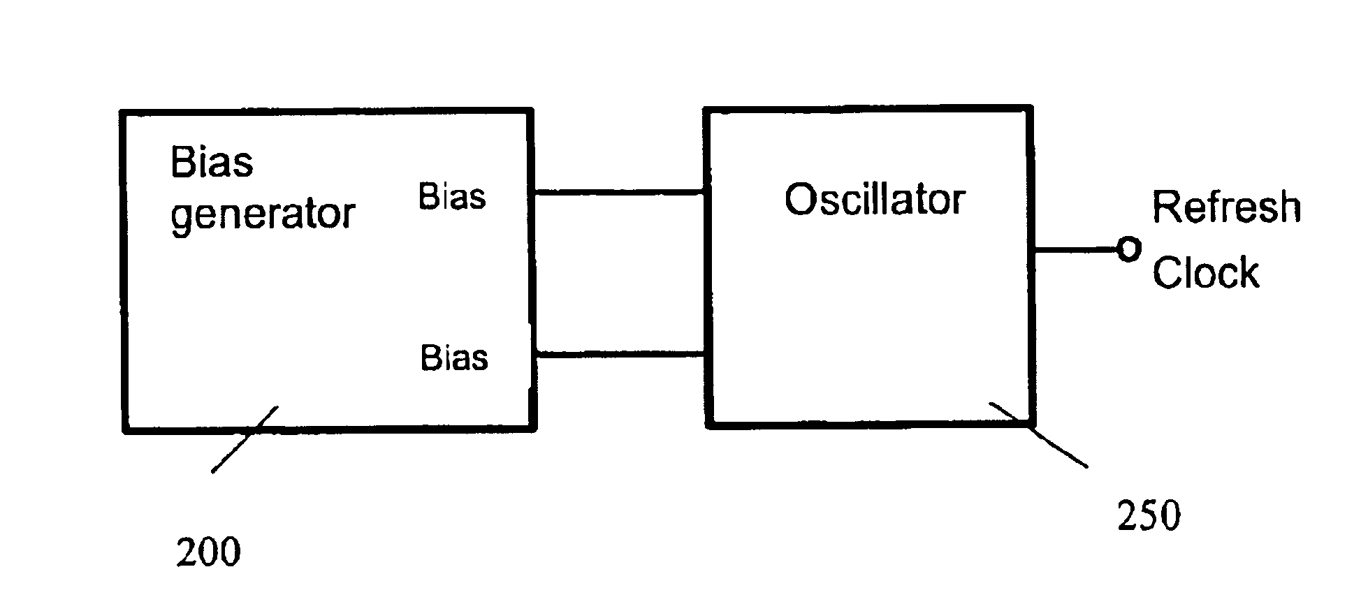
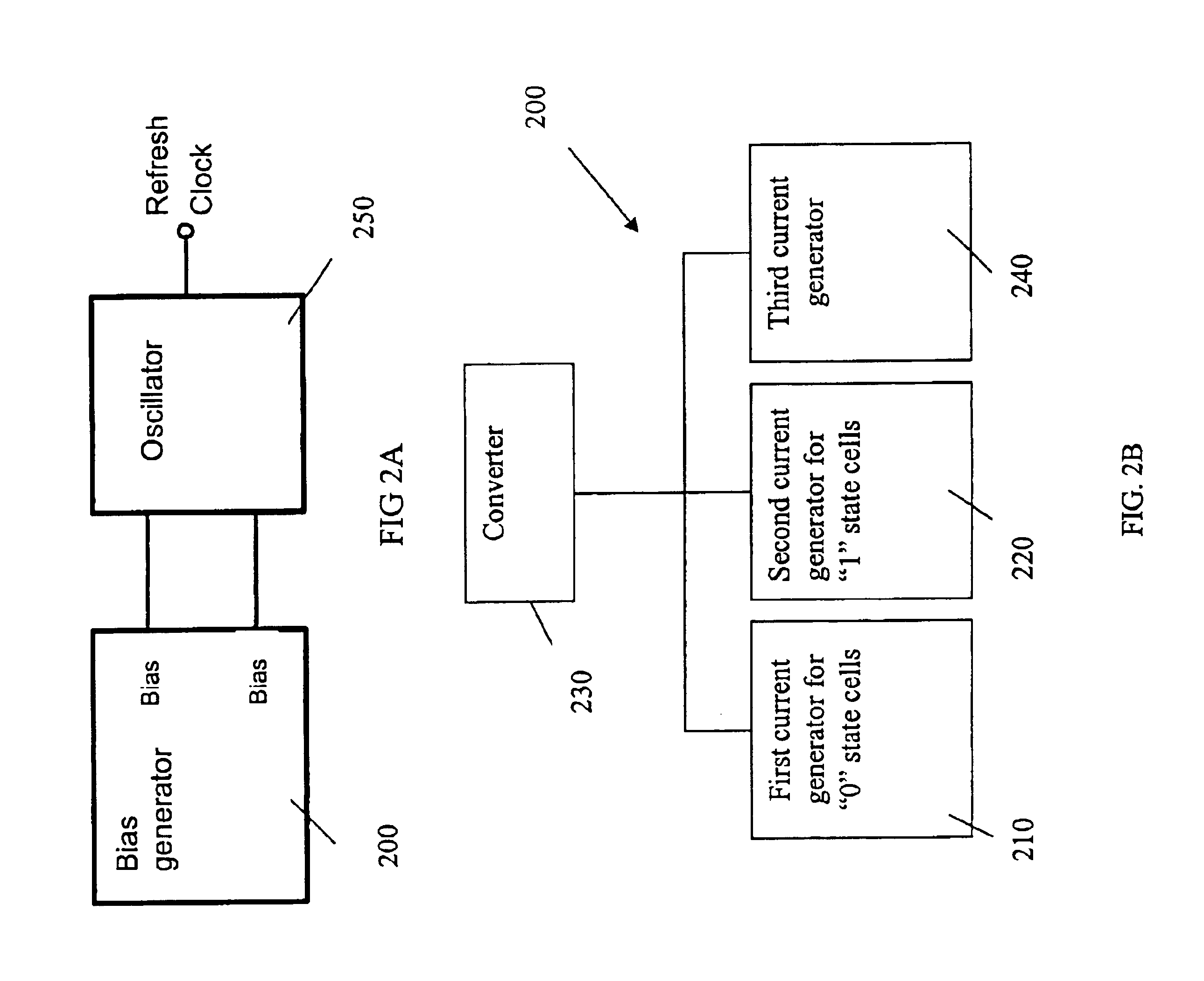
FIG. 2A illustrates a schematic block diagram of an exemplary circuit for generating a periodic pulse signal for cell self refresh. The circuit comprises bias generator 200 and oscillator 250.

Bias generator 200 is adapted to accumulate leakage currents generated from one or more memory cells and generate one or more output biases for determining a self refresh period. The output biases may then be applied to oscillator 250 for generating a periodic signal pulse in response to the leakage currents.

FIG. 2B is a schematic block configuration illustrating the exemplary bias generator 200 illustrated in FIG. 2A. In the embodiment illustrated in FIG. 2B, bias generator 200 comprises first current generator 210, second current generator 220, third current generator 240, and converter 230. In certain embodiments, if one leakage current fully dominates, the other current generator, e.g. 210 or 220, may not be necessary due to its negligible current contribution.

First current generator 210 is...


PUM


Abstract

A circuit and a method for self refresh of DRAM cells are provided. The circuit comprises a bias generator and an oscillator. The bias generator comprises a first current generator, a second current generator and a converter. The first current generator generates a first leakage current of “0” state cells. The second current generator generates a second leakage current of “1” state cells. The converter transforms a current comprising the first leakage current and the second leakage current into output biases. The method comprises generating leakage currents from memory cells; transforming the leakage currents into output biases for determining a self refresh period; and using the output biases to control an oscillator for generating a periodical signal pulse in response to the leakage currents.

Description

FIELD OF THE INVENTIONThe present invention relates to a circuit and its method of use for semiconductor integrated circuits; more particularly, the present invention relates to a circuit and a method for self refresh of dynamic random access memory (DRAM) cells.DESCRIPTION OF THE RELATED ARTIn dynamic random access memory (DRAM), one cell structure in a DRAM array is predominantly made of one-transistor memory cells, each of which comprises a selection transistor and a storage capacitor. The selection transistor serves as a switch and the capacitor is used for storing electric charges which represent data. For example, the terminal voltage of the capacitor determines the binary information stored therein. A high terminal voltage could represent a “1” and a low terminal voltage could represent a “0” or the opposite could be the case. A “write” operation is performed when a voltage corresponding to the binary information is applied to the memory cell. A “read” operation occurs when t...

Claims


Application Information

Patent Timeline
IPC IPC(8): G11C11/406
CPCG11C11/406G11C11/40615G11C2211/4068
Inventor HUANG, CHIEN-HUACHOU, CHUNG-CHENG
Owner TAIWAN SEMICON MFG CO LTD
Why Eureka
Try Eureka