
System and method for process variation monitor

a technology of process variation and monitor, which is applied in the field of system and method for optically monitoring variation, can solve the problems of unintentional deviation of process at any step, defects in some features of the ic, and high complexity of the process of fabricating integrated circuits (ics) on semiconducting substrates such as silicon wafers, and achieve the effect of more accurate or reliable results

Inactive Publication Date: 2005-03-01
APPL MATERIALS ISRAEL LTD
View PDF6 Cites 23 Cited by
  • Summary
  • Abstract
  • Description
  • Claims
  • Application Information

AI Technical Summary

Benefits of technology

In one embodiment of the invented system, partial results of the defects detection operation are further processed to directly obtain indications of process variations over the entire inspected area. Also in common with the defects detection operation, the invented method can advantageously use the outputs of any multiple sensors comprised in the inspection system, such as those disposed along various angles to the inspected surface and to the illuminating beam, including sensing a so-called dark field or a so-called bright field, to sense more varied effects and thus obtain more accurate or more reliable results. The invented method can also form a basis for a capability of classifying process variations whose effects have been detected and measured by it, although the embodiments to be described below do not include such a capability.

Problems solved by technology

The process of fabricating integrated circuits (ICs) on a semiconducting substrate, such as a silicon wafer, is highly complex and consists of a large number of steps.
There are, however, physical factors that may cause unintentional deviations in the process at any step.
When any of these—process deviations becomes excessive, singly or in combination, defects may appear in some features of the IC.
They may be due to microscopic disturbances in the process, such as dust particles, or they may be, as they often are, extreme manifestations of macro-defects.
It may be carried out by means of the same equipment, but often is done on a separate, very high resolution, device, such as a scanning electron microscopes (SEM)—which is extremely expensive.
This current-art procedure of learning about process deviations that cause macro-defects in the fabricated ICs by detecting micro-defects, and possibly reviewing them, has two major drawbacks: Firstly and most importantly, macro-defects must be fairly severe in order for detectable resultant micro-defects to appear; there is then a risk of deleterious further deviation in the process before it is remedied; in extreme cases, the detected defects, whether micro or macro, may already be excessive, requiring wafer rejection—which obviously represents economical loss.
Secondly, the close examination and analysis of defects during the review phase involves time and costly equipment; the time delay may cause additional wafers to be adversely affected before the process deviations have been identified and corrected.
It is noted that the first drawback could be averted if the entire surface could be inspected at high resolution; this procedure is, however, extremely slow and, as mentioned above, requires very expensive equipment.

Method used


Image

  • System and method for process variation monitor
  • System and method for process variation monitor
  • System and method for process variation monitor

Examples


Embodiment Construction

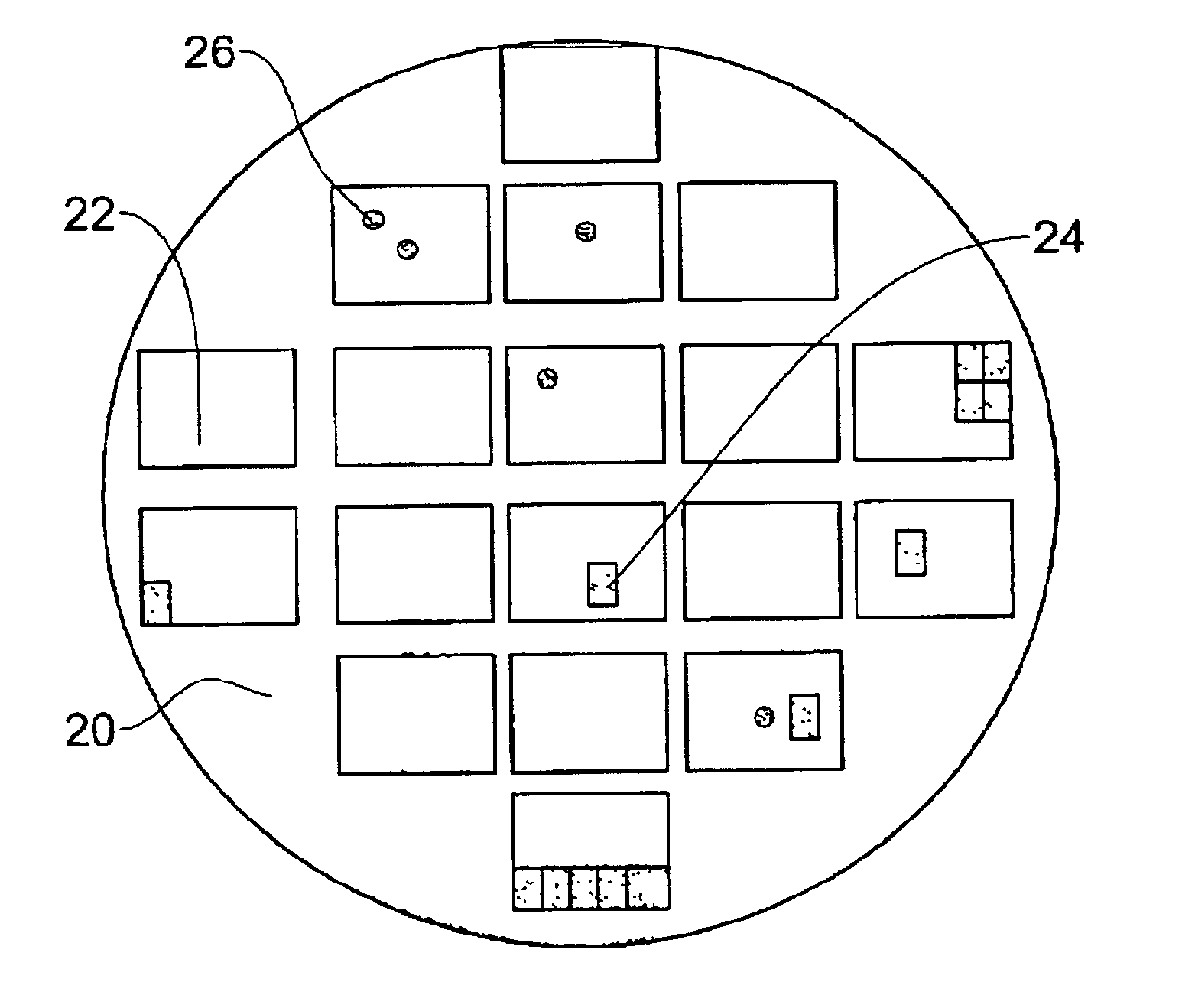
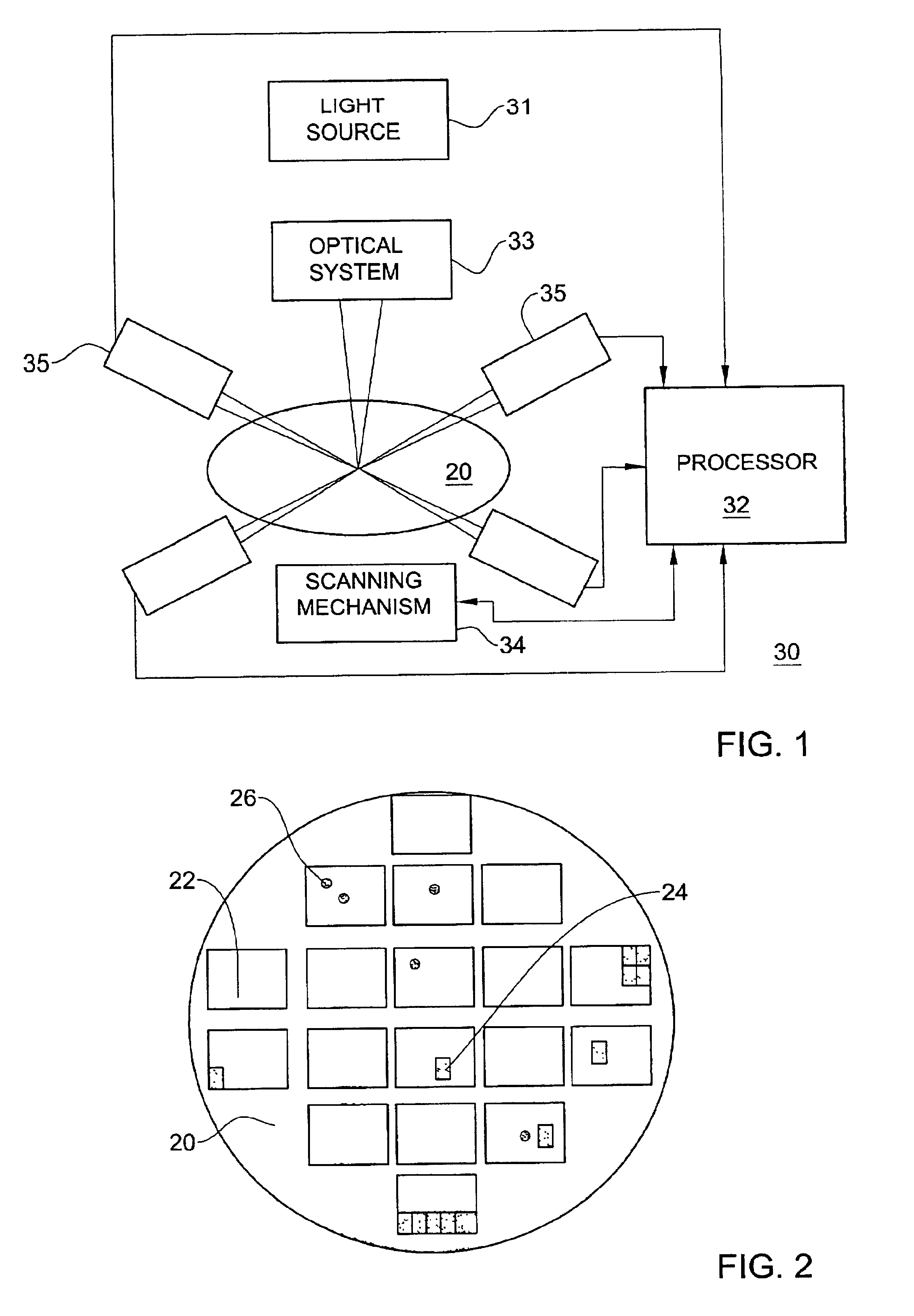
The method of the invention is preferably embodied as an additional computer program, runable on a digital processor resident in a wafer inspection system, which normally serves to detect defects after certain wafer processing stages. A particular example of such an inspection system, which will be used herein to illustrate the method, is the Compass inspection system, sold by Applied Materials of Santa Clara Calif., mentioned in the Background section above and shown schematically in FIG. 1. It should however be understood that the method of the invention can also be embodied, with obvious modifications, as an appropriate program on any processor in other inspection systems, including those that serve to inspect surfaces other than semiconductor wafers. It should likewise be understood that the method of the invention can also be embodied, with obvious modifications, in a system specifically or solely designed for it, for the purpose of process variation monitoring only.

In the insp...


PUM


Abstract

A method to extend the process monitoring capabilities of a semiconductor wafer optical inspection system so as to be able to detect low-resolution effects of process variations over the surface of a wafer at much higher sensitivity than heretofore possible. The method consists, in essence, of grouping sensed pixels by geometric blocks over the inspected surface and comparing each block with a corresponding one from another die on the same wafer, from another wafer or from a stored model image. In one embodiment of the invention, pixel values are compared directly and differences are thresholded at a considerably lower level than during a defects detection process. In another embodiment, there is calculated a signature for each block, based on the sensed light intensity values, and corresponding signatures are compared.

Description

FIELD OF THE INVENTIONThis invention relates to the field of semiconductor wafer inspection and, in particular, to a system and method for optically monitoring variations in the integrated-circuit fabrication process.BACKGROUND OF THE INVENTIONThe process of fabricating integrated circuits (ICs) on a semiconducting substrate, such as a silicon wafer, is highly complex and consists of a large number of steps. Each step involves many process parameters that must be tightly controlled in order to obtain consistent and accurate results. There are, however, physical factors that may cause unintentional deviations in the process at any step. Such factors may be due to variations in the substrate itself, to slight mechanical and optical inaccuracies in the processing equipment (such as defocusing due to slight misalignment), to dust and dirt and to environmental variations. The deviations in the process may be a function of time, that is—between successive wafers, or between various parts ...

Claims


Application Information

Patent Timeline
IPC IPC(8): G01N21/88G01N21/95G01N21/956G06T7/00H01L21/66
CPCG01N21/9501G01N21/956G06T7/001G01N21/95607G06T2207/30148G01N2021/8896Y10S430/146H01L22/00
Inventor LEVIN, EVGENIALMOGY, GILADROZENMAN, EFRAT
Owner APPL MATERIALS ISRAEL LTD
Learn More