
Method for manufacturing fiber aggregate, fiber aggregate, and liquid container using such fiber aggregate

a technology of fiber aggregate and fiber aggregate, which is applied in the field of manufacturing fiber aggregate, fiber aggregate, and liquid container using such fiber aggregate, can solve the problems of acid-denatured chlorinated polypropylene not soluble in water, the effect of short resistance to air

Inactive Publication Date: 2005-03-08
CANON KK
View PDF17 Cites 23 Cited by
  • Summary
  • Abstract
  • Description
  • Claims
  • Application Information

AI Technical Summary

Benefits of technology

The present invention provides a method for manufacturing a fiber aggregate with improved uniformity in its property. The method involves forming a fiber surface with a hydrophilic processing liquid containing polymer, and then orientating the polymer to bond the contact points of fibers. The invention also provides a liquid supply method and a liquid supply unit using the non-processed portion or low-processed portion of the fiber, which can enhance the uniformity of the fiber aggregate. The use of a hydrophilic processing liquid containing polyalkylsiloxane with hydrophilic group, acid, alcohol, and water is preferred for providing the hydrophilic property to the fiber surface. The small aggregate formed by crimped short fibers with uniform fiber direction can be thermally bonded effectively.

Problems solved by technology

However, the resultant effect thereof does not last long.
Also, it is impossible to coat uniformly up to the inside of a fine element or a porous object.
Particularly, acid-denatured chlorinated polypropylene is not soluble against water, and cannot be made water soluble.
The use thereof is limited accordingly.
With the conventional surface reformation only by means of chemical binding using radical process, a uniform surface reformation cannot be made on the surface having a complicated configuration.
Here, in particular, no surface reformation can be effectuated in the inferior of a negative pressure generating member that has a complicated porous portion inside, such as a complex fiber element arranged to generate negative pressure to be used in the field of ink jet technology.
In addition, any method that uses the liquid, in which surface active agent is contained, is not effective in reforming the surface of porous object itself, and when the surface active agent is no longer present, its property is lost completely.
Moreover, olefinic resin is excellent in water-repellent property having a contact angle of 80 degrees or more to water, but there is no surface reforming method therefor to make a desired hydrophilic property obtainable for a long time.

Method used


Image

  • Method for manufacturing fiber aggregate, fiber aggregate, and liquid container using such fiber aggregate
  • Method for manufacturing fiber aggregate, fiber aggregate, and liquid container using such fiber aggregate
  • Method for manufacturing fiber aggregate, fiber aggregate, and liquid container using such fiber aggregate

Examples


first embodiment

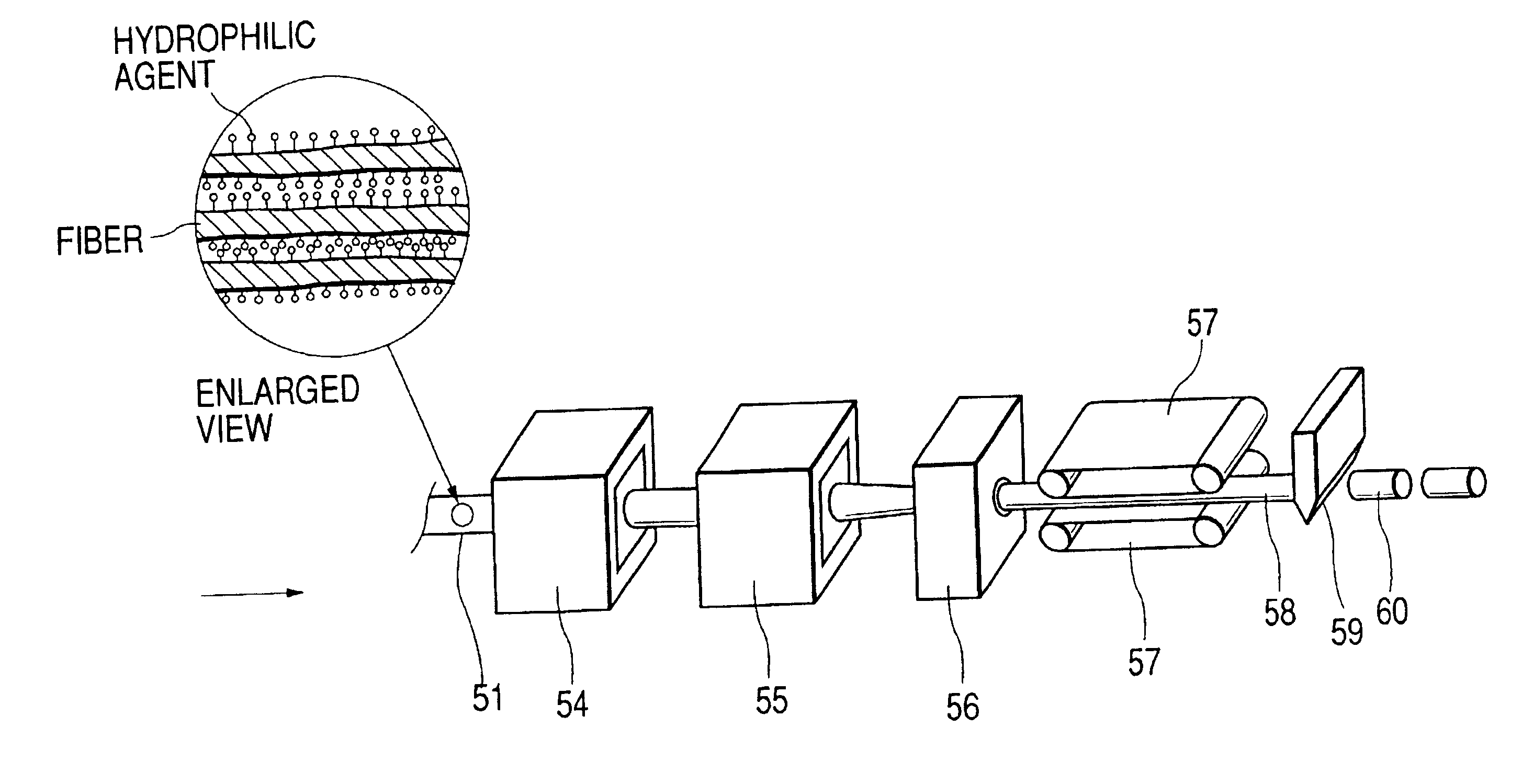
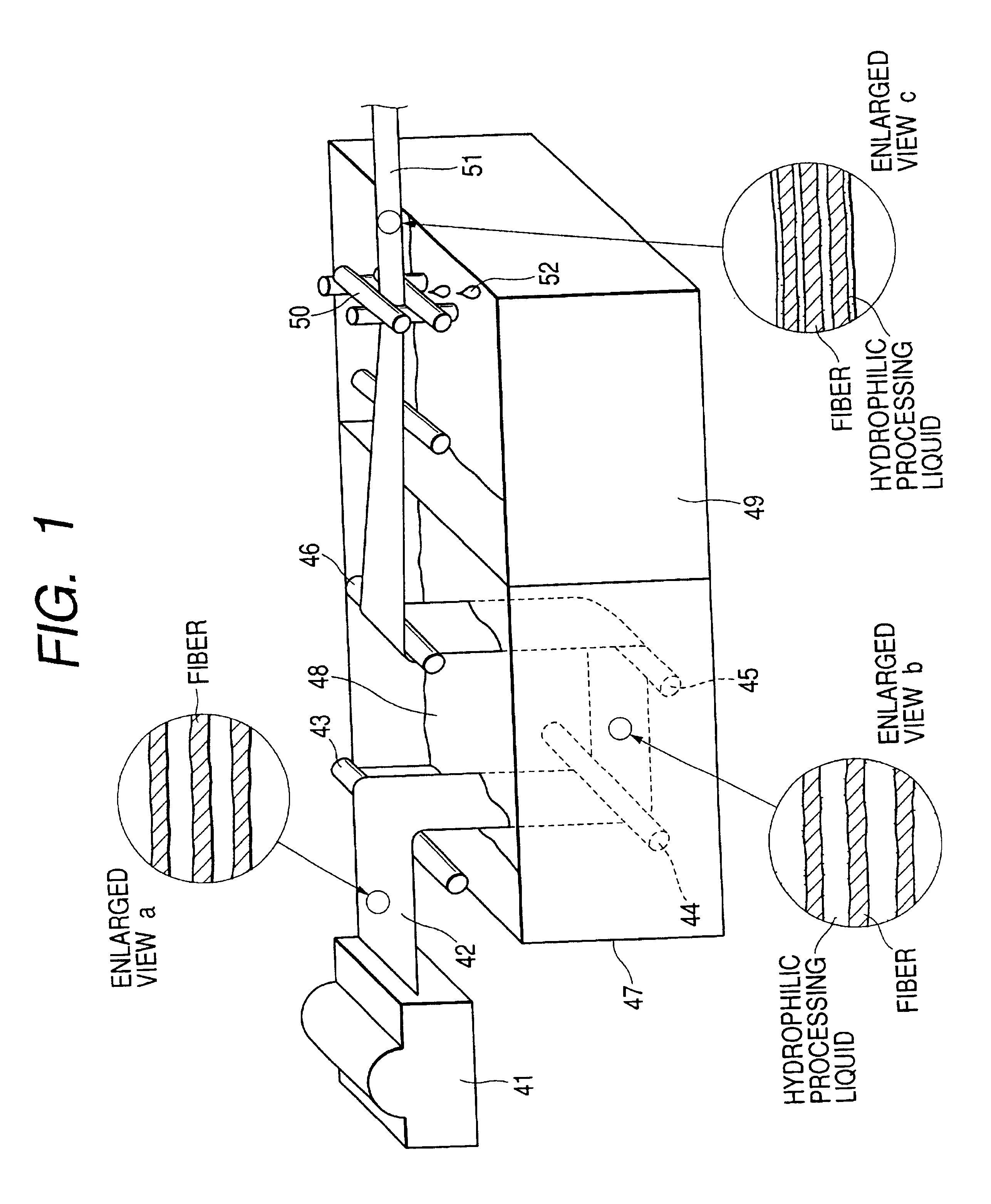
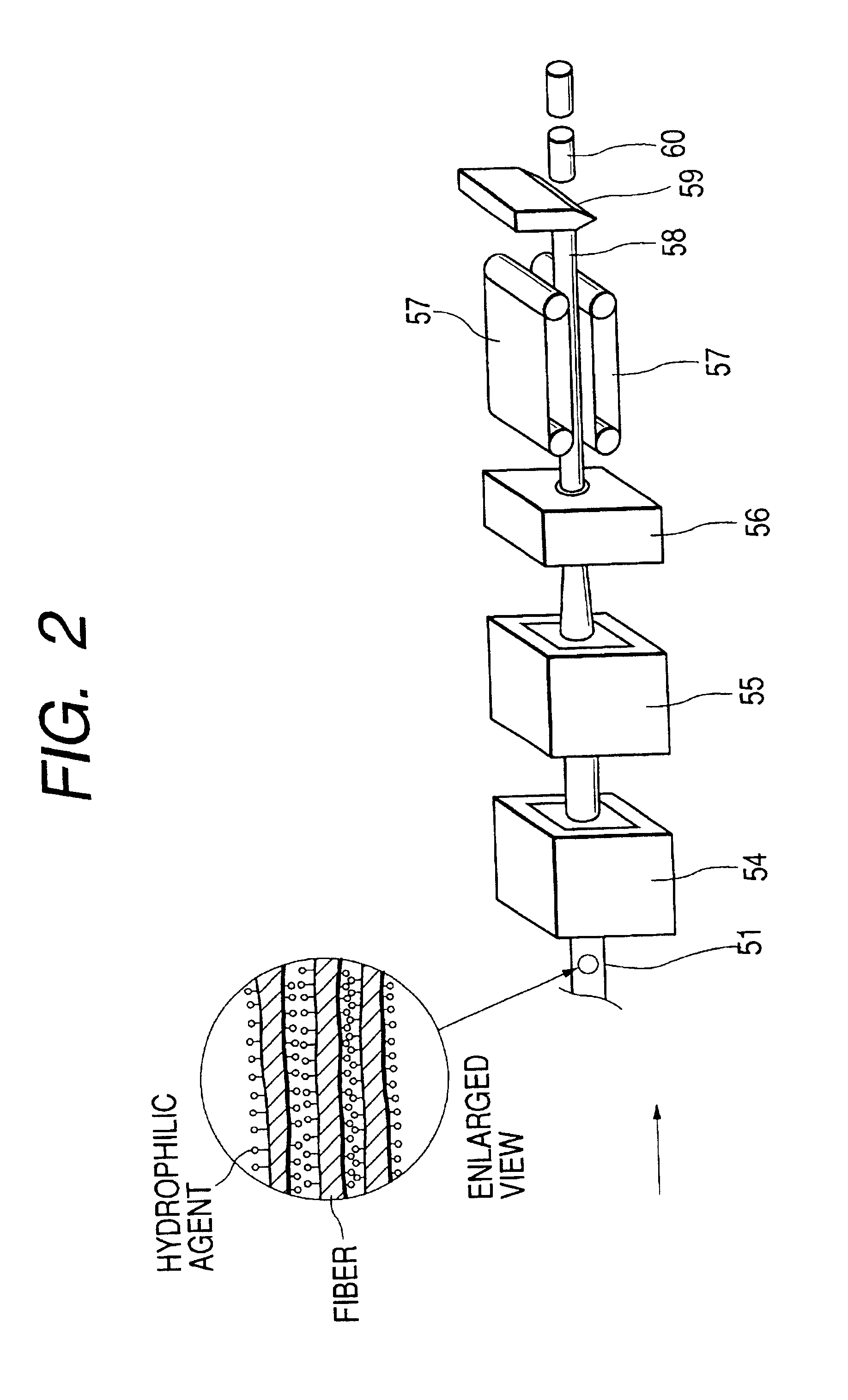
FIG. 1 is a view which shows the characteristics of a method for manufacturing a fiber aggregate in the base way in accordance with a first embodiment of the present invention. FIG. 2 is a view which illustrates in continuation the manufacturing process shown in FIG. 1. FIGS. 3A and 3B are cross-sectional views of fiber used for the present embodiment. FIG. 4 is a flowchart which illustrates the method for manufacturing a fiber aggregate in accordance with the first embodiment of the present invention. FIGS. 5A to 5D, and FIG. 6 are views which illustrate the structure of the fiber aggregate of the present embodiment.

In FIG. 1, after cutting the tow that gathers two kinds of thermoplastic synthetic fibers (or may be more than two kinds of them) having different fusion points, the tow thus cut is carried by air brow to pass a cotton comber 41. Then, the fiber that has been entangled complicatedly is disentangled to enable the fiber direction thereof to be substantially uniform (see a...

second embodiment

The first embodiment describes the example in which the fiber surface is reformed in the state of sliver. Here, however, the description will be made of the example in which the fiber surface is reformed in the stage of the simple fiber as shown in FIGS. 7A and 7B, and FIGS. 8A and 8B.

For the single fiber of the present embodiment, the thermoplastic synthetic fiber of biaxial structure, which is formed by polypropylene as the core material and polyethylene as the casing material, is used (see FIGS. 3A and 3B), but it should be good enough if fiber used is the environment friendly olefine resin, such as polyethylene of monoaxial structure. The synthetic fiber is roughly classified into filament (long fiber) and staple (short fiber). FIGS. 7A and 7B are views which schematically illustrate the manufacturing process of filament, and FIGS. 8A and 8B, that of staple.

In a case of the long fiber (filament), spinning is executed as shown in FIG. 7A by cooling material resin by use of an air...

third embodiment

The fiber aggregate manufactured as described above has cut section and non-cut section on the surface of fiber aggregate due to the method of manufacture, and the characteristics are different with respect to liquid by the cut section and non-cut section. In other words, the non-cut section is formed mostly by the hydrophilic processed fiber surface and presents hydrophilic property as shown in FIG. 6. However, the cut section is mostly formed by the section of biaxially structured synthetic fiber of PP and PE, and the wettability is unfavorable (the contact angle of PP and PE to water is 80° or more).

Here, therefore, the description will be made of an example to utilize the characteristics of the method for manufacturing fiber aggregate as described above. FIGS. 10A and 10B are cross-sectional views which schematically illustrate an ink tank used for an ink jet apparatus preferably applicable to the fiber aggregate obtainable by the method of manufacture of the present invention. ...


PUM

PropertyMeasurementUnit
contact angleaaaaaaaaaa
temperatureaaaaaaaaaa

Abstract

A method for manufacturing a fiber aggregate formed by fiber having reforming surface comprises the steps of providing a fiber surface having thermoplastic resin at least on the surface layer thereof with a hydrophilic processing liquid containing polymer having a first portion with more hydrophilic group than the surface, and a second portion having interfacial energy different from that of the hydrophilic group, and interfacial energy substantially equal to the surface energy of the fiber; orientating the second portion toward the fiber surface, while orientating polymer to the side different from the surface of the first group; and forming a fiber absorber by heating the fiber having the reformed surface in the step of orientating polymer to thermally bond the contact points of fibers themselves. With this method of manufacture, it becomes possible to enhance the uniform property of the fiber aggregate still more, which is formed subsequent to making the property of such fiber aggregate uniform per unit of single fiber or small aggregate existing in any one of stages before the formation thereof.

Description

BACKGROUND OF THE INVENTION1. Field of the InventionThe present invention relates to a method for manufacturing a fiber aggregate having the fiber surface which has been given a reforming process. The invention also relates to a liquid supply method that utilizes a fiber aggregate manufactured by such method of manufacture, and an ink supply unit as well.2. Related Background ArtThe ink tank used for an ink jet recording apparatus contains absorber in the tank to keep ink by means of the inner pressure exerted by such absorber, and maintains meniscus stably at the ink discharge portion of a recording head.As one of ink adsorbents that generate negative pressure in an ink tank of the kind, there is a fiber element that holds ink between entangled fibers by use of capillary force. For this fiber element, the fiber, which is formed by polyorefine resin having polyethylene (PE) formed on the surface layer of polypropylene (PP), is practically used from the viewpoint of recycling capabil...

Claims


Application Information

Patent Timeline
Patent Type & Authority Patents(United States)
IPC IPC(8): B41J2/175D01F8/06D01F11/00D01F11/06D01F6/04D01F6/06D04H1/541D04H1/544D06M15/643
CPCB41J2/17513B41J2/17556D06M23/14D06M15/647D06M23/08D06M11/55
Inventor SANADA, MIKIOSUGAMA, SADAYUKIHATTORI, SHOZOYAMAMOTO, HAJIMESHIMIZU, EIICHIROKOSHIKAWA, HIROSHIHAYASHI, HIROKIKITABATAKE, KENJI
Owner CANON KK
Learn More