Flue gas treating system and process

a technology of flue gas treatment system and process, which is applied in the direction of separation process, sulfur compound, sulfate preparation, etc., can solve the problems of large-scale and high-cost equipment disadvantage, increased cost, and certain limits

Inactive Publication Date: 2005-03-08
MITSUBISHI HEAVY IND LTD
View PDF23 Cites 34 Cited by
  • Summary
  • Abstract
  • Description
  • Claims
  • Application Information

AI Technical Summary

Problems solved by technology

However, when ammonia is injected in ordinary amounts, this catalyst is omitted because the amount of slipping ammonia is very slight.
In the above-described conventional flue gas treatment, the large-sized and high-cost equipment has been disadvantageous.
This requires an ample space between boiler house 1 and stack 13, and a plurality of flues and a large number of supporting members therefor, resulting in an increased cost.
This has also been difficult in the construction of the conventional system.
However, this is contrary to the desire for a reduction in size and hence has a certain limit.
In such a case, the conventional system has used ammonia decomposition catalyst 2b in order to remove any ammonia slipping to the downstream side, resulting in a corresponding increase in cost.
Moreover, a considerable portion of the flues and its supporting members becomes unnecessary, and the main body of the stack becomes much shorter than before.
Moreover, in this case, the heat exchanger does not allow air to leak into the flue gas.
Furthermore, when a region in which a liquid having higher acidity than the absorbing fluid is sprayed so as not to allow ammonia to be easily released into the gaseous phase is created on the downstream side of the region of the absorption tower in which the flue gas is brought into gas-liquid contact with the absorbing fluid, whereby the ammonia remaining in the flue gas introduced into the desulfurization step is absorbed in the absorption tower without allowing it to remain in the flue gas leaving the absorption tower, an adverse effect due to the excessive injection of ammonia (i.e., the emission of ammonia into the atmosphere) can be avoided.

Method used


Image

  • Flue gas treating system and process
  • Flue gas treating system and process
  • Flue gas treating system and process

Examples


first embodiment

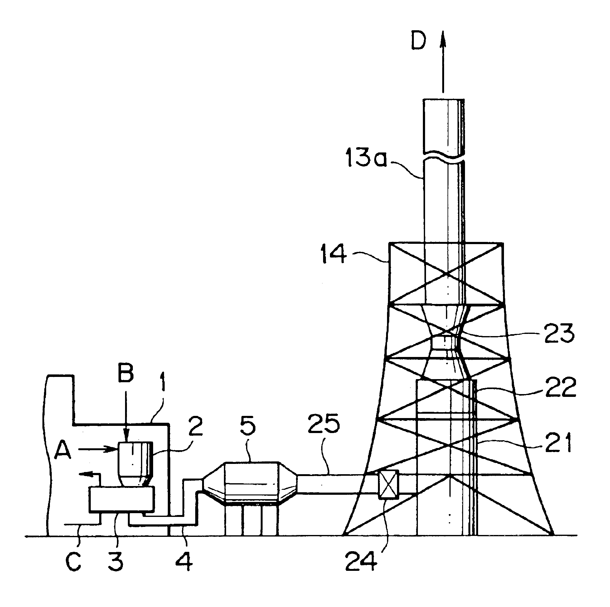
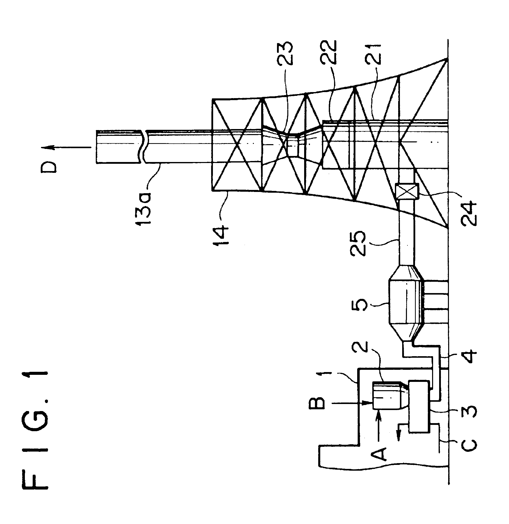
A first embodiment of the present invention is described with reference to FIG. 1. The same elements as included in the conventional system of FIG. 9 are designated by the same reference numerals, and the duplicate explanation thereof is omitted.

The flue gas treating system of this embodiment is characterized in that, below the main body 13a of a stack, an absorption tower 21, the reheating section 22 of a gas-gas heater, and a fan 23 are arranged in line on the vertical axis of the stack so as to form part of the stack.

The heat recovery section 24 of the gas-gas heater is installed at a position which is on the way of a flue 25 connecting a dry electrostatic precipitator 5 with absorption tower 21 and on the inside of the framework 14 for the stack. Eventually, all of absorption tower 21, the heat recovery section 24 and reheating section 22 of the gas-gas heater, and fan 23 are all installed in an unoccupied space on the inside of the framework 14 for the stack.

In this embodiment,...

second embodiment

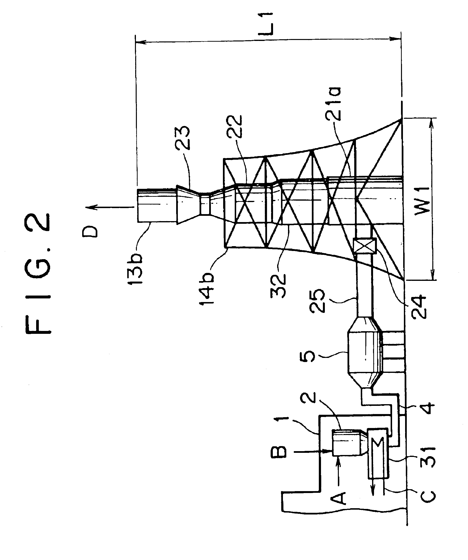
Next, a second embodiment of the present invention is described with reference to FIG. 2. The same elements as included in the first embodiment are designated by the same reference numerals, and the duplicate explanation thereof is omitted.

This embodiment is characterized in that it is equipped with an air heater (or heat exchanger) 31 comprising a non-leakage type heat exchanger of shell-and-tube structure, and a wet electrostatic precipitator 32 is installed between absorption tower 21a and reheating section 22. In this embodiment, the aforesaid air heater 31 and the previously described heat recovery section 24 of the gas-gas heater constitute a heat exchanger for carrying out the heat recovery step of the present invention. Moreover, the dry electrostatic precipitator 5 described in connection with the conventional system serves to carry out the first dust removal step of the present invention, and the aforesaid wet electrostatic precipitator 32 serves to carry out the second du...


PUM

PropertyMeasurementUnit
widthaaaaaaaaaa
acidityaaaaaaaaaa
temperatureaaaaaaaaaa

Abstract

In a flue gas treating system, an absorption tower (21), a reheating section (22) and a fan (23) are arranged in line on a vertical axis so as to function as at least a part of a stack for emitting the treated flue gas into the atmosphere. Moreover, in a flue gas treating process, the amount of ammonia injected in the denitration step (a denitrator (2)) and/or the amount of ammonia at a point downstream of the denitration step are determined so as to be on such an excessive level that ammonia or ammonium salt will remain in the flue gas introduced into the desulfurization step (absorption tower (21)). Thus, the size and cost of the equipment can be reduced.

Description

FIELD OF THE INVENTION AND RELATED ART STATEMENTThis invention relates to a flue gas treating technique for effecting at least the denitration and desulfurization of flue gas. More particularly, it relates to a flue gas treating technique which makes it possible to reduce the size of the equipment and enhance the performance of the equipment.Conventionally, in order to remove nitrogen oxides, sulfur oxides (typically sulfur dioxide) and dust (e.g., fly ash) present in flue gas discharged from a boiler of a thermal electric power plant or the like, an exemplary flue gas treating system or process as illustrated in FIGS. 9 and 10 is widely employed. This flue gas treating technique is described hereinbelow.As illustrated in FIG. 9, untreated flue gas A discharged from a boiler (not shown in FIG. 9) is first introduced into a denitrator 2 installed in a boiler house 1, so that nitrogen oxides present in the flue gas are decomposed. Denitrator 2 functions to decompose nitrogen oxides ac...

Claims


Application Information

Patent Timeline
Patent Type & Authority Patents(United States)
IPC IPC(8): C01B17/00C01B17/96B01D53/60
CPCB01D53/60B01D53/77
Inventor KOTAKE, SHINICHIROKIMURA, KAZUAKISUZUKI, KAZUMITSUUKAWA, NAOHIKOTAKASHINA, TORU
Owner MITSUBISHI HEAVY IND LTD
Why Eureka
Try Eureka