Switch apparatus

Active Publication Date: 2005-03-08
OMRON AUTOMOTIVE ELECTRONICS CO LTD
View PDF15 Cites 6 Cited by
  • Summary
  • Abstract
  • Description
  • Claims
  • Application Information

AI Technical Summary

Benefits of technology

[0082]As described above, the prior art (second prior art) according to the inventors of the invention is advantageous in that it can avoid contact damage without inviting the drastic increase

Problems solved by technology

When the switch apparatus is applied to an electric system having a higher voltage such as the 42V electric system, however, a large current flows through the contacts connected to the negative plate power source during the return from the UP state to t

Method used


Image

  • Switch apparatus
  • Switch apparatus
  • Switch apparatus

Examples


Embodiment Construction

switch C, return feeling of the switch C from the closed state to the open state can be improved.

BRIEF DECRIPION OF THE DRAWINGS

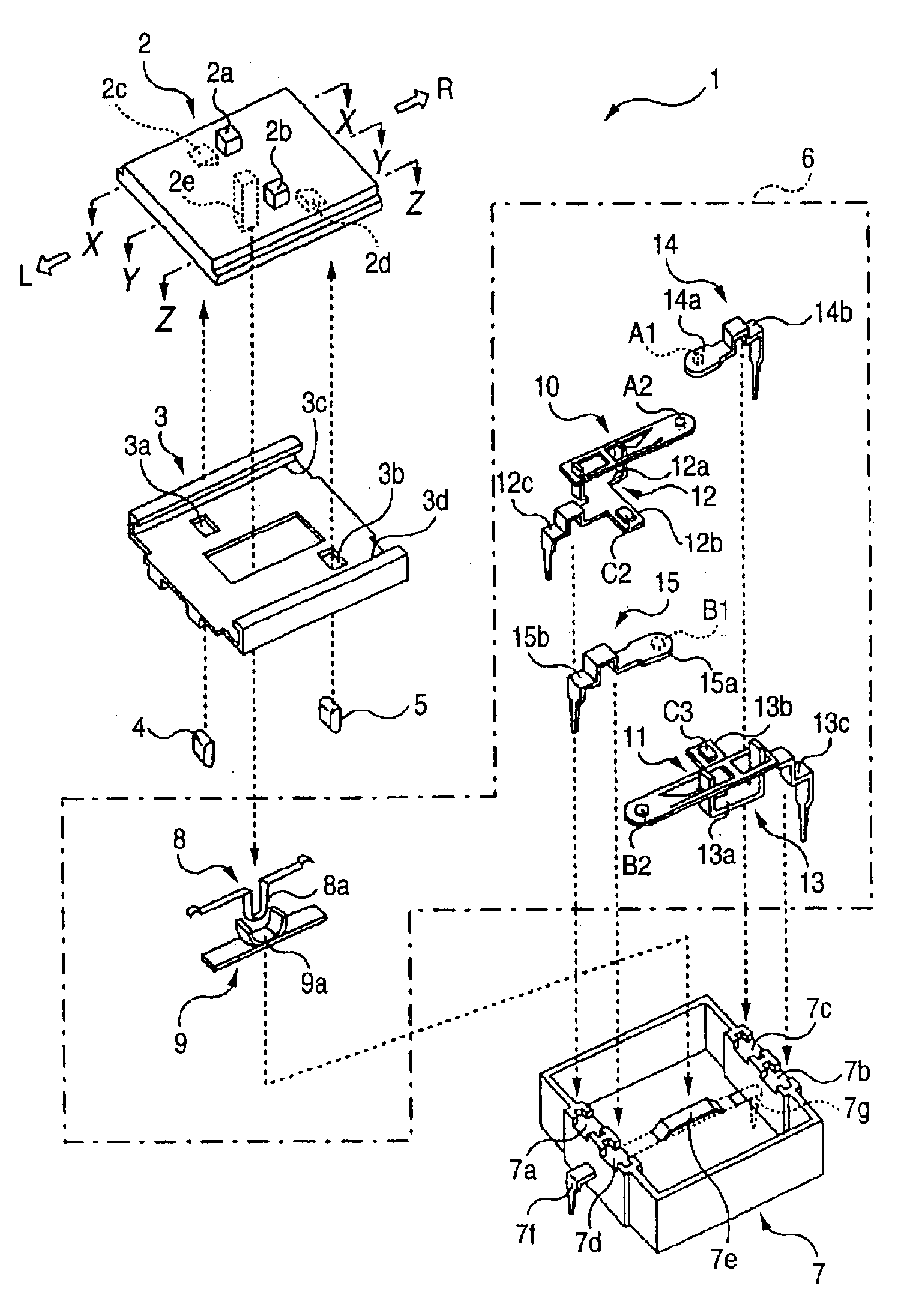
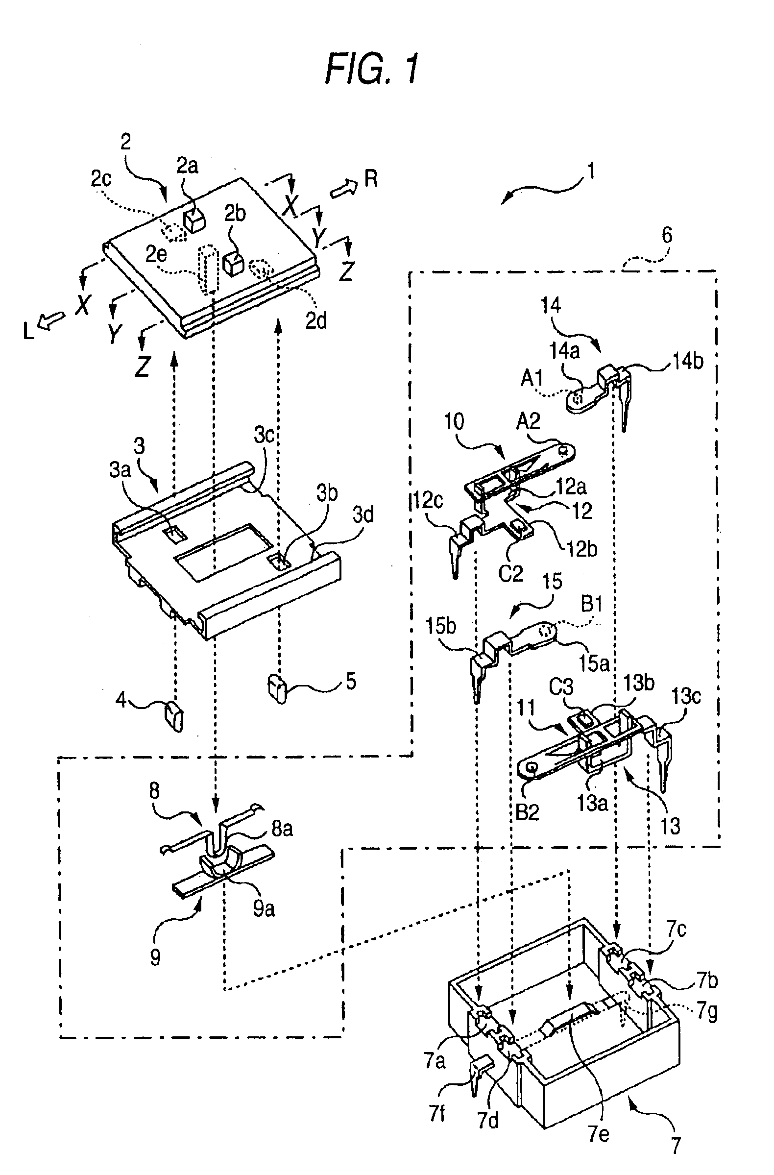
[0091]FIG. 1 is an exploded view of a switch apparatus 1 according to an embodiment of the invention;

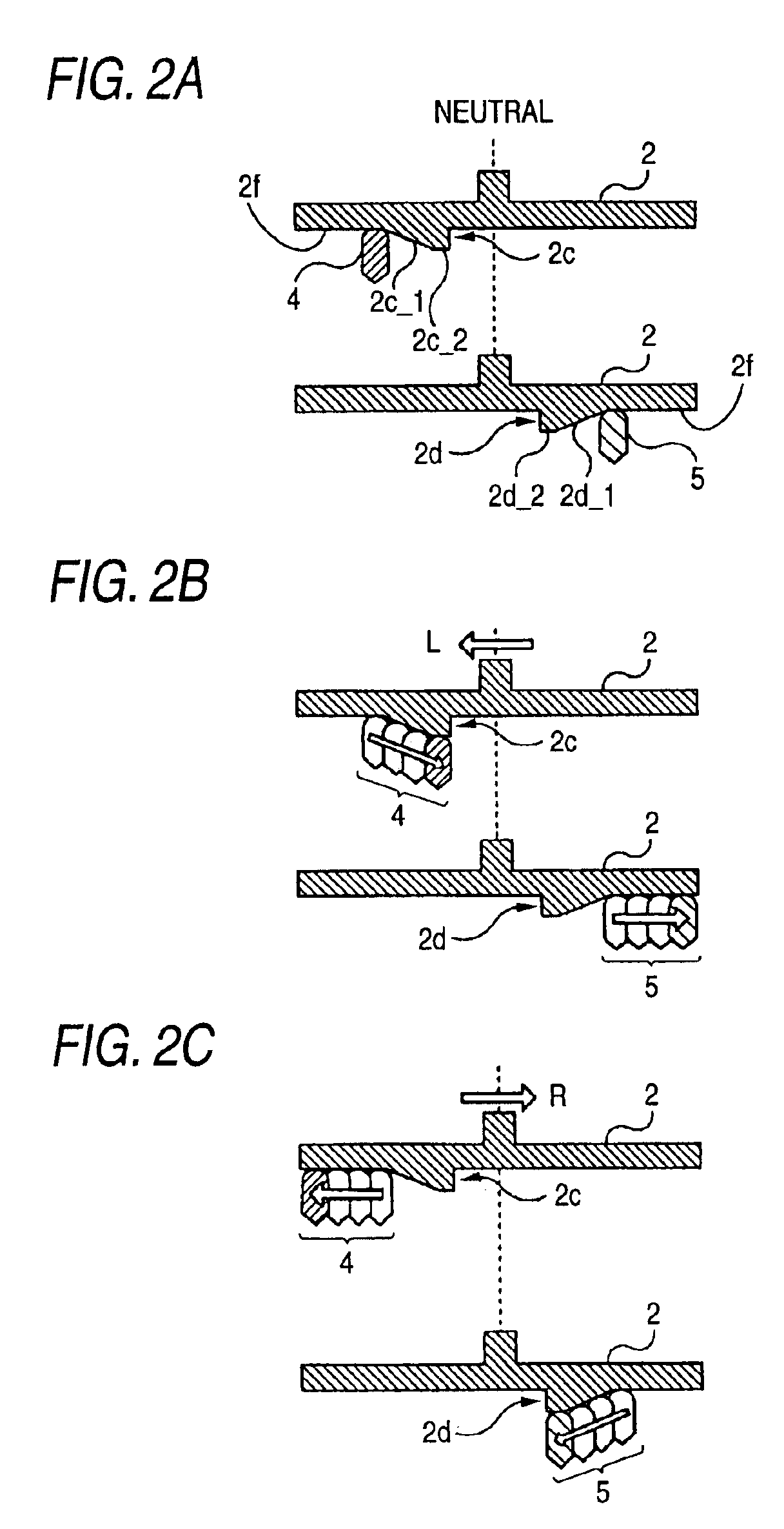
[0092]FIG. 2 is a sectional view of a slider taken along a line X—X and along a line Z—Z;

[0093]FIG. 3 is a view showing a contact switching state of two metal leaf spring type moving plates 10 and 11;

[0094]FIG. 4 shows a structure of a switch C;

[0095]FIG. 5 shows a switching state of the switch C;

[0096]FIG. 6 is a circuit diagram of the switch apparatus 1;

[0097]FIG. 7 is a diagram showing correspondence of state between a contact-switching operation of switches A, B and C and a stop / rotation operation of a DC motor 101;

[0098]FIG. 8 is circuit diagrams respectively showing first and second modified examples of the switch apparatus 1;

[0099]FIG. 9 is circuit diagram showing third to fifth modified examples of the switch apparatus 1;

[0100]FIG. 10 is a structural...


PUM


Abstract

A switch apparatus of the invention can avoid contact damage without inviting a drastic increase in a size even when applied to a high power source voltage and does not deteriorate return feeling to a neutral state. The switch apparatus includes a switch A for cutting off connection between one side driving input of a DC motor and a negative plate side power source, a switch B for cutting off connection between the other side driving input and the negative plate side power source, and a switch C for cutting off connection between the one side driving input and the positive plate side power source and connection between the other side driving input and the positive plate side power source, wherein the switch A and the switch B are normally-closed type switches and the switch C is a normally-open type switch. The switch C is opened at a predetermined time before the switch A or the switch B is closed, and cuts off in advance a power source route to avoid the occurrence of dead short-circuit. When the switch C has a slide type structure, switch feeling of contacts of the switch C can be improved.

Description

BACKGROUND OF THE INVENTION[0002]1. Field of the Invention[0003]This invention relates to a switch apparatus for rotating and stopping a DC motor for opening and closing windows of a vehicle such as an automobile, for example, or DC motors used for similar applications. More particularly, the invention relates to a switch apparatus that will be used appropriately for a DC motor operating at a high power source voltage (in a 42 V electric system, for example).[0004]2. Description of the Related Art[0005]Prior Art: Re: 42 V Electric System[0006]Existing automobiles have employed a 14 V electric system. As the number of electronic appliances mounted to the automobiles has increased, however, it,has become more difficult for the 14 V electric system to meet required power consumption. To solve this problem, an industry-university cooperation consortium has reached after intensive global discussion the consensus that a threefold higher voltage system, that is, “42 V system”, be employed ...

Claims


Application Information

Patent Timeline
IPC IPC(8): H01H15/00H01H15/10E05F15/16B60R16/02H01H23/30
CPCH01H15/102E05Y2900/55E05F15/695H01H2300/01
Inventor SHIMIZU, KEIICHITANAKA, YASUHIDEYAMAGUCHI, KIYOTAKA
Owner OMRON AUTOMOTIVE ELECTRONICS CO LTD
Why Eureka
Try Eureka