Method and circuits for controlling the power of an electronically switched, two-phase reluctance machine

Inactive Publication Date: 2005-03-08
ELECTRIC DRIVE TECH
View PDF4 Cites 38 Cited by
  • Summary
  • Abstract
  • Description
  • Claims
  • Application Information

AI Technical Summary

Benefits of technology

The aim of this invention is to indicate possibilities of the power control of SR machines without additional expensive power semi-conductors. It should be considered here that the efficiency of the machine should remain as high as possible. This means that the recovery of the demagnetization energy should take place ef

Problems solved by technology

If the feedback of the self-induction voltage over the transistors would have been renounced to, this would have resulted in a waste further transmission of the by-pass current to the other phase of the wrong moment, wit

Method used


Image

  • Method and circuits for controlling the power of an electronically switched, two-phase reluctance machine
  • Method and circuits for controlling the power of an electronically switched, two-phase reluctance machine
  • Method and circuits for controlling the power of an electronically switched, two-phase reluctance machine

Examples


Embodiment Construction

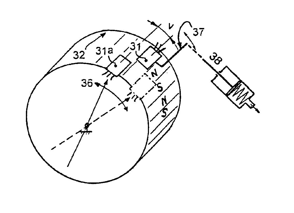
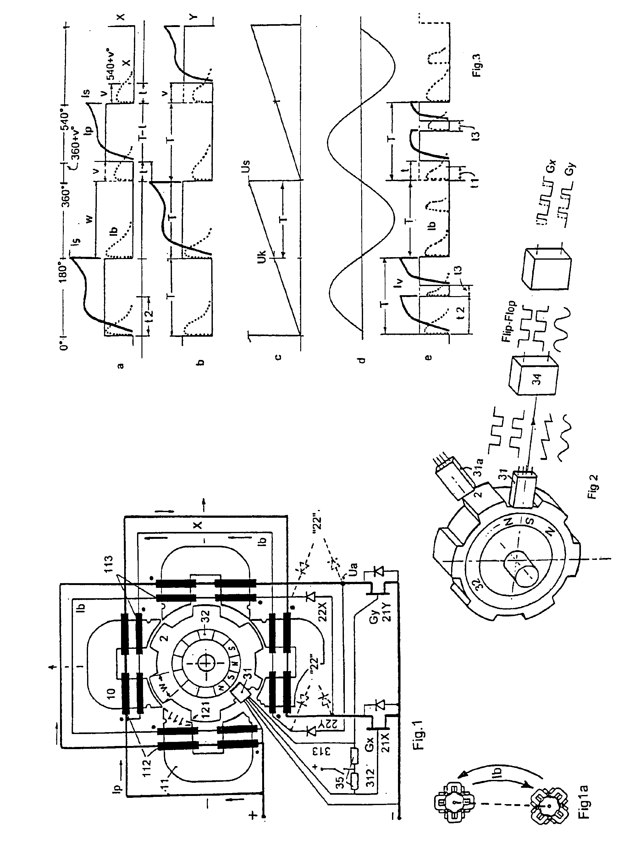
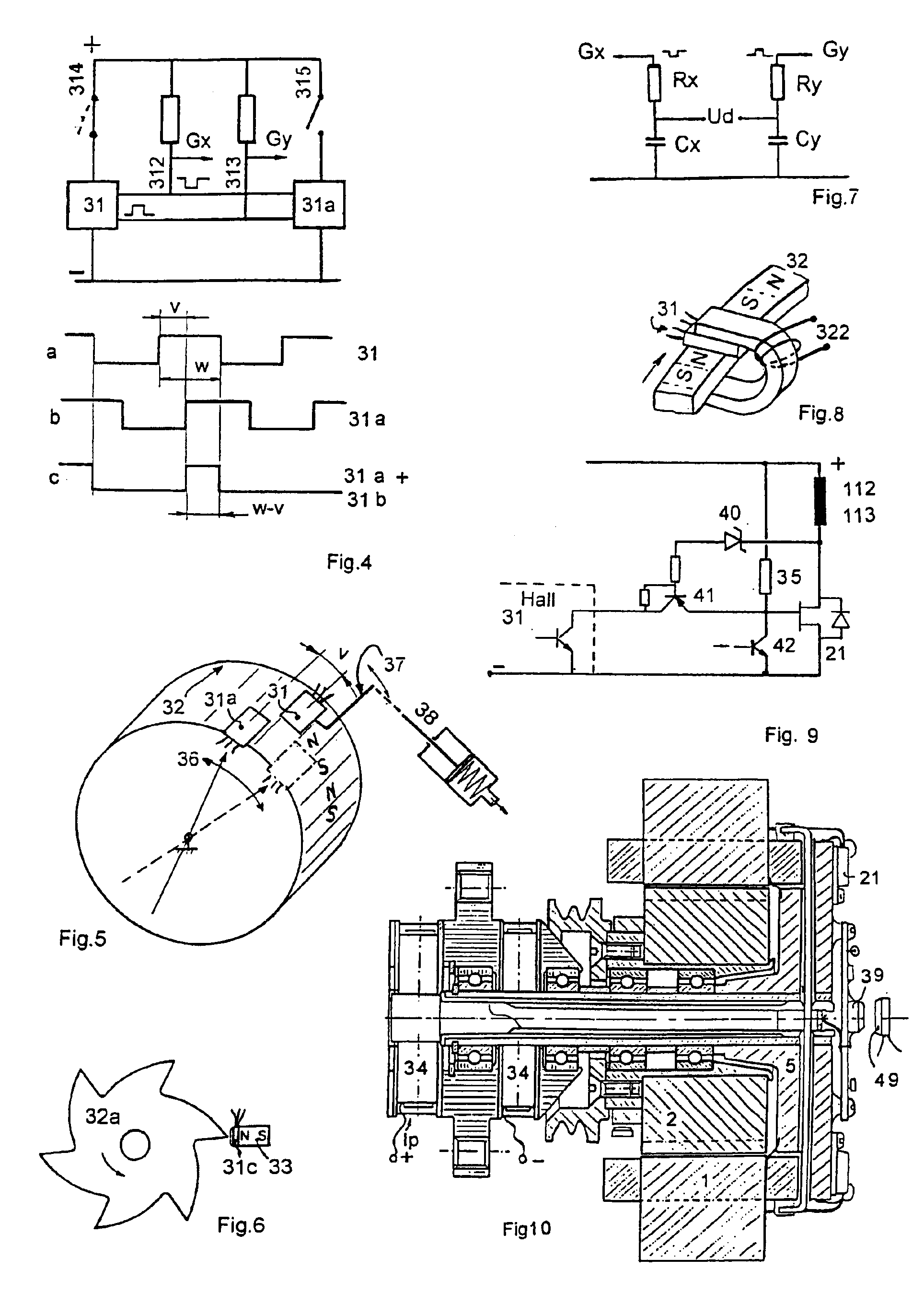
FIG. 1 shows such a simple but operative motor, for an easier understanding in a compressed form (magnetic circuit and circuit). Each individual of the eight main windings (112) and secondary windings (113) is represented as an inductive resistor fixed on the sketched magnet yoke 11. The main current paths (see “definitions”) are represented by fat or thicker lines in the accompanying drawings. The simplest circuit (see FIG. 1) of an uncontrolled SR motor works in the sense of the invention, as known from the prior art, with a Hall sensor 31 with two complementary “flip-flop” open-collector outputs 312, 313 as phase control which has been realistically sketched in the vicinity of the rotor. The gate electrodes of the power switches 21X, 21Y, which receive voltage for example over the polarization pull-up resistor 35, are alternatively short-circuited to the minus potential (ground) over the Hall sensor outputs 312, 313 so that the main current is thus interrupted. For an uncontrolle...


PUM


Abstract

The present invention provides principles and circuits for the power control of two-phase switched reluctance machines featuring a direct recovery of the phase switch-off energy and a 180° phase angle at full load. The power control method of the present invention does not require any supplementary power switches and acts through the logic circuitry upon the existing power switches of a motor which formerly did not exhibit a power control. The power control relies physically on a shorter current flow or duty cycle after the phase beginning. This can be done either through mechanical phase shift of a second Hall sensor or by using time delay circuits.

Description

BACKGROUND OF THE INVENTIONThe invention relates to electronically switched, two-phase reluctance machines (motors or generators, also called SR machines—switched reluctance machines) which have a particular magnetic circuit as know, for example, from the international patent applications WO 96 / 09683 and WO 98 / 23024.Because of the magnetic circuits known from the prior art which allow a very simple, highly efficient recovery of the demagnetization energy of a just switched-off phase, up to now the instantaneous supplying of the second motor phase with current had to take place at the moment of the switching-off of the first one.In order to achieve a power control, it has been proposed to interrupt the main current before the end of the phase. The current flow in this phase to be switched-off should be maintained up to the end of the phase duration due to the feedback of the self-induction voltage by means of two additional power transistors, such as that disclosed in WO 96 / 409683. T...

Claims


Application Information

Patent Timeline
IPC IPC(8): H02K29/06H02P25/08H02P25/02H02K29/08H02K19/02H02K19/10H02K16/00H02P6/00
CPCH02K19/103H02P25/082H02P25/081H02K29/08H02K16/005H02P25/0925H02P25/089
Inventor LUNGU, IANCU
Owner ELECTRIC DRIVE TECH
Why Eureka
Try Eureka