
Low profile, dual polarized/pattern antenna

Inactive Publication Date: 2005-03-08
HRL LAB
View PDF14 Cites 27 Cited by
  • Summary
  • Abstract
  • Description
  • Claims
  • Application Information

AI Technical Summary

Benefits of technology

[0022]In one aspect, this invention utilizes a spiral antenna to provide efficient radiation and / or reception of circularly polarized signals in a direction approximately 30 to 70 degrees from the axis of the spiral and, simultaneously, linearly polarized signals in a direction closer to the plane of the spiral. In the preferred embodiment, the spiral antenna provides efficient radiation and / or reception of circularly polarized signals in a direction approximately 45 degrees from the axis of the spiral. Simultaneous reception of both circularly and linearly polarized signals is achieved by exciting the spiral antenna in two ways. A feed network is preferably utilized which has two outputs that are routed to a radio transmitter and / or a radio receiver. A transceiver could be used if the antenna system is used for both receiving and transmitting signals. The primary advantage of this antenna system is that the antenna patterns may be optimized for receiving simultaneous terrestrial and satellite links while preferably still maintaining a low profile (for example, a height less than a quarter wavelength).

Problems solved by technology

DBS radio systems typically have a narrow bandwidth (about 0.5%) due to the low power available from satellites, as well as the problems associated with mobile wireless communications.
The drawback of this antenna is that it typically protrudes more than one-half wavelength from the surface of wherever it is mounted and, thus, if it is mounted on the exterior surface of a vehicle, it results in an unsightly and unaerodynamic vertical structure.

Method used


Image

  • Low profile, dual polarized/pattern antenna
  • Low profile, dual polarized/pattern antenna
  • Low profile, dual polarized/pattern antenna

Examples


Embodiment Construction

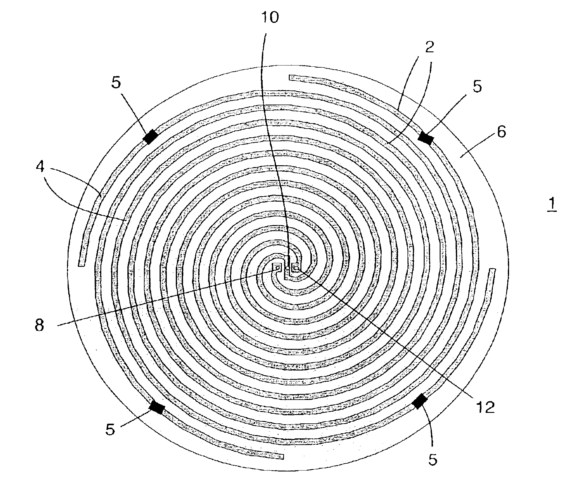
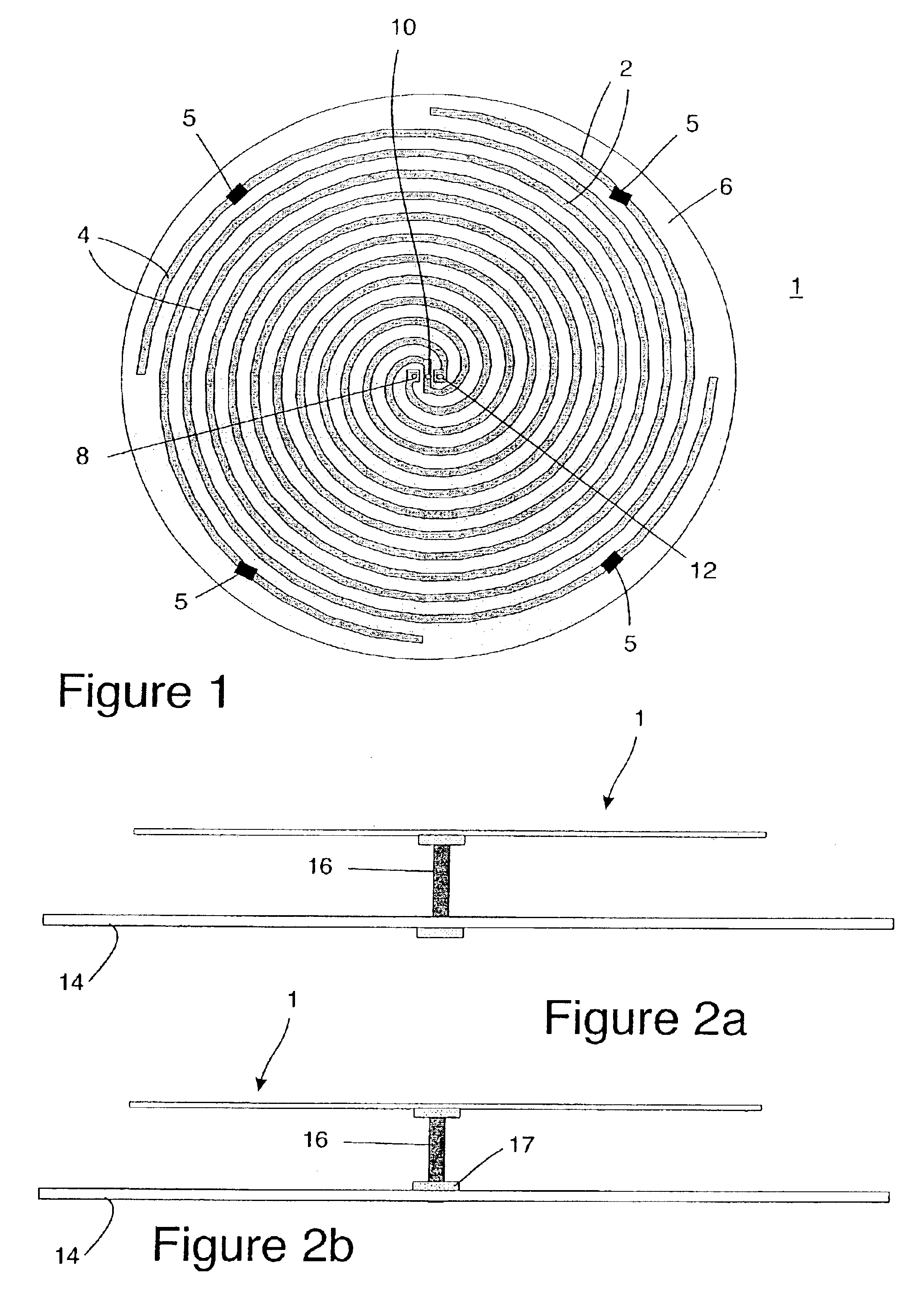
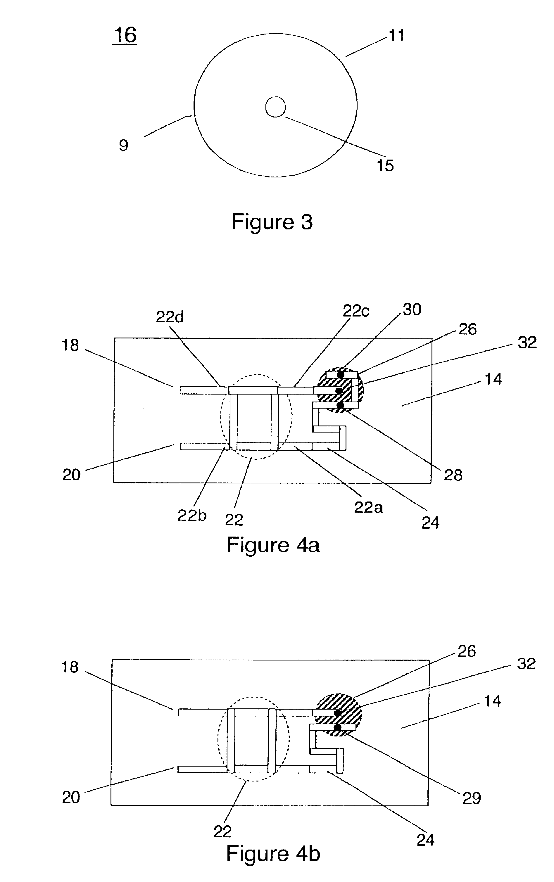
[0041]In accordance with the present invention, a spiral antenna 1 (see FIG. 1) may be operated in one of three different modes. These modes are generated by exciting the arms of the spiral with a phase shift between adjacent arms that is based the total number of arms, n, in the spiral. In one embodiment (mode 1), a 360 / n degree phase shift is applied between adjacent arms. In another embodiment (mode 2), a 720 / n degree phase shift is applied between adjacent arms, and for a third embodiment (mode 3), a 1080 / n degree phase shift is applied between adjacent arms. Each of these embodiments (modes in this case) generates a different radiation pattern. In a preferred embodiment, the spiral antenna is operated in mode 2 and the spiral is optimized for use in a DBS system such as the XM Satellite Radio system, which uses a frequency band of 2.3325 GHz to 2.345 GHz. In mode 2, where the spiral antenna has 4 arms (n=4), the phase shift is equal to 720 / 4 or 180 degrees.

[0042]FIG. 1 is a dep...


PUM


Abstract

A spiral antenna system optimized to transmit and / or receive linearly polarized signals and circularly polarized signals. The antenna system includes a spiral antenna and a circuit for exciting the spiral antenna to transmit or receive linearly polarized and circularly polarized signals simultaneously.

Description

CROSS REFERENCE TO RELATED APPLICATION[0002]This application claims the benefits of U.S. Provisional Patent Application 60 / 388,097 filed Jun. 10, 2002, the disclosure of which is hereby incorporated hereby by this reference.FIELD OF THE INVENTION[0003]The present invention relates to antenna systems which may be used on vehicles to communicate with both a satellite and a terrestrial system.BACKGROUND OF THE INVENTION[0004]There is currently a need for antennas and / or antenna systems that can communicate with both a satellite and a terrestrial system. One example of such a need is for a Direct Broadcast Satellite (DBS) radio in which radio signals are broadcasted from a satellite and are received by a receiver located on the vehicle and are also received by terrestrial repeaters which rebroadcast the signals therefrom to the same vehicle. Typically, a DBS uses circular polarization so the vehicle can receive the transmission in any orientation. However, terrestrial networks typically...

Claims


Application Information

Patent Timeline
IPC IPC(8): H01Q21/24H01Q9/04H01Q9/36H01Q21/00H01Q21/28H01Q9/27
CPCH01Q9/27H01Q21/28H01Q21/24H01Q9/36
Inventor LYNCH, JONATHAN J.COLBURN, JOSEPH S.
Owner HRL LAB
Learn More