Optical apparatus

a technology of optical equipment and optical components, which is applied in the field of optical equipment, can solve the problems of high cost and time-consuming manufacturing, observer fatigue in viewing stereoscopic video images, and the inability to fuse images, etc., and achieves excellent mobility and expandability, small size, and low cost.

Inactive Publication Date: 2005-03-08
CANON KK
View PDF7 Cites 59 Cited by
  • Summary
  • Abstract
  • Description
  • Claims
  • Application Information

AI Technical Summary

Benefits of technology

It is, therefore, an object of the invention to provide an image pickup apparatus which is small in size, low in cost and excellent in mobility and expandability and is capa...

Problems solved by technology

However, since, in the case of the above-mentioned conventional twin-lens type stereoscopic camera, a video image for the right eye and a video image for the left eye are picked up for the respective lenses, if the difference between the two lenses in performance, such as magnification, deviation of an optical axis, color, brightness, distortion, field tilt or the like, occurs due to the manufacturing error of lenses, the observer tends to feel tired in viewing a stereoscopic video image, or two images tend to be unable to fuse with each other.
Therefore, the twin-lens type stereoscopic camera having zoom lenses necessitates high cost and a time-consuming job for manufacturing and has low mass-productivity.
In addition, two monitors are naturally needed for observing video...

Method used


Image

  • Optical apparatus
  • Optical apparatus
  • Optical apparatus

Examples


second embodiment

Next, a stereoscopic video photographing apparatus according to the invention is described.

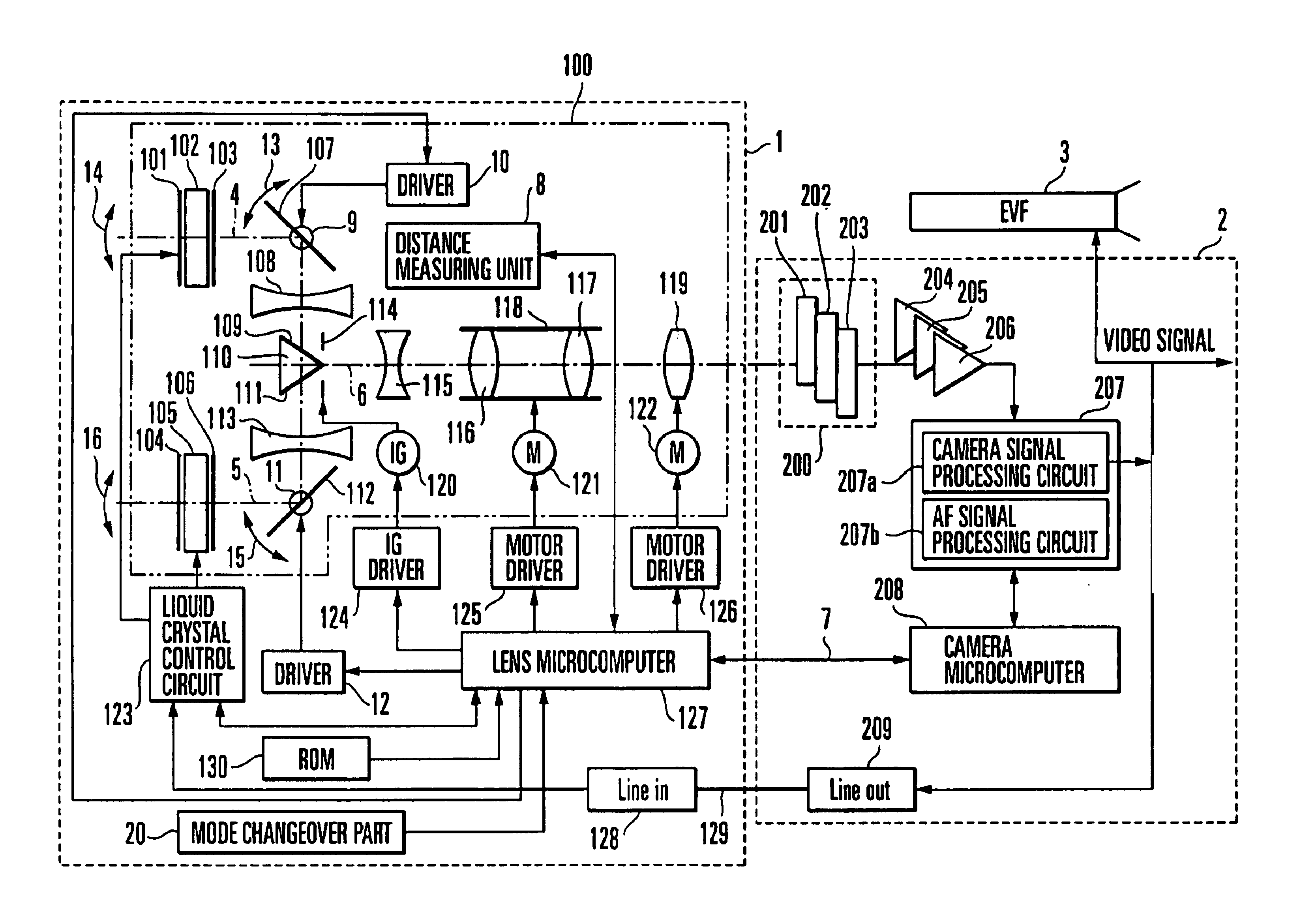
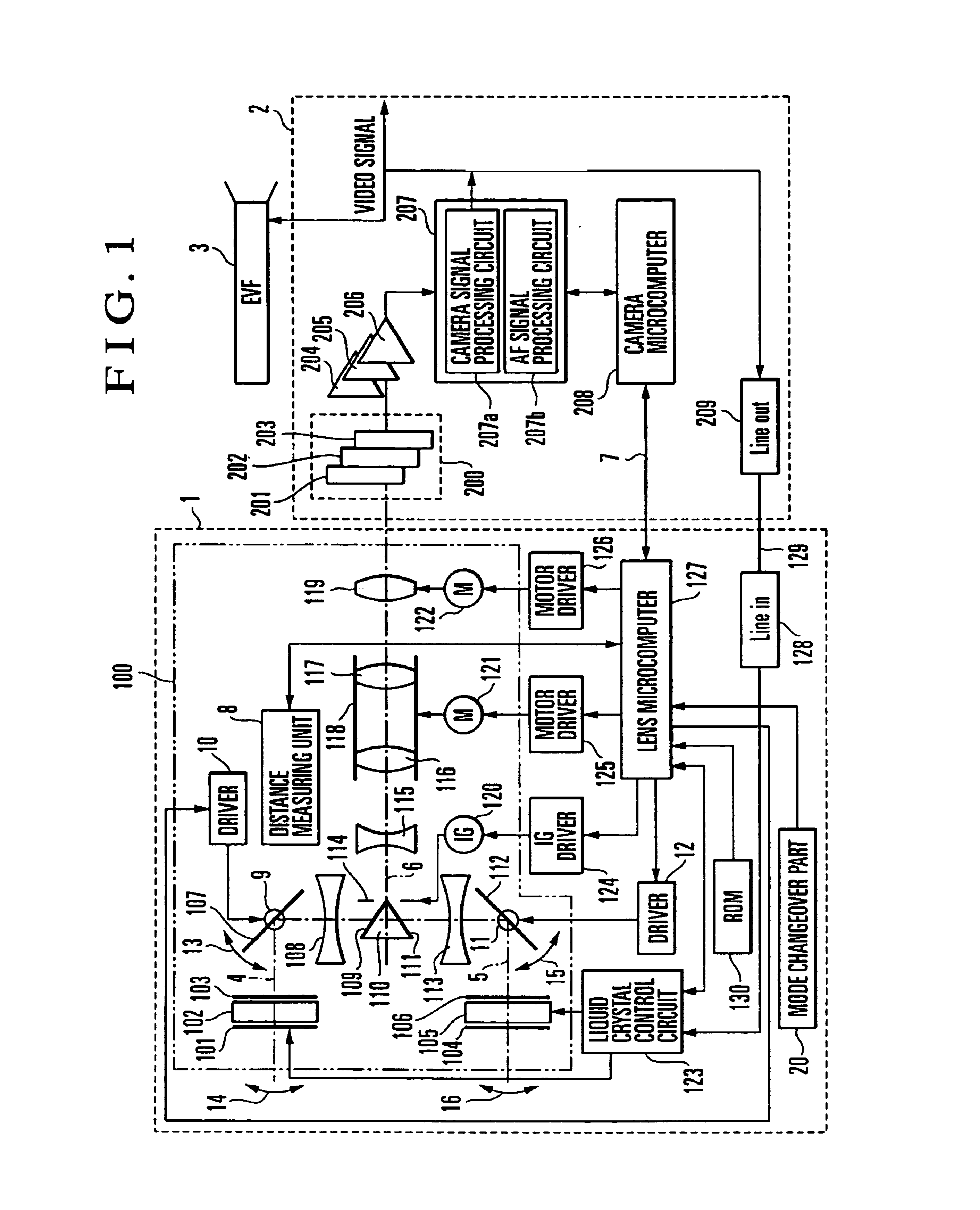
The construction of the stereoscopic video photographing apparatus according to the second embodiment is the same as the block diagram shown in FIG. 1, and the duplicate description is omitted herein. The characteristic feature of the second embodiment is that the respective distance measurement areas of an automatic focus adjusting means of the camera body 2 and an object-distance detecting part (distance measuring unit) 8 of the lens unit 1 are made to overlap each other, so that it is possible to naturally and automatically control the convergence distance.

FIG. 9 is a diagram showing distance measurement areas set in a reading area 22 of a CCD 200a serving as the image sensor 200. As shown in FIG. 9, the distance measurement areas 81, 82 and 83 for the object distance L to be detected by the distance measuring unit 8 are set at three portions, i.e., the left-side portion, the middle portion...

third embodiment

Next, a stereoscopic video photographing apparatus according to the invention is described.

FIG. 11 is a block diagram showing the basic construction of the stereoscopic video photographing apparatus according to the third embodiment of the invention.

The construction shown in FIG. 11 differs from the block diagram of FIG. 1 in that there is provided a display information input part 21 for inputting, to the lens microcomputer 127 within the lens unit 1, information on the screen size of a display apparatus for displaying a stereoscopic video image and information on the distance from the eyes of the observer to the screen of the display apparatus.

By this arrangement, it becomes possible to perform the optimum convergence control for the display apparatus.

Specifically describing, in the process for deciding the convergence distance in step S8 in the flow chart of FIG. 6 showing the above-described convergence control, the optimum convergence control is performed on the basis of informa...

fourth embodiment

Next, a stereoscopic video photographing apparatus according to the invention is described.

As mentioned in the foregoing, there is a twin-lens type stereoscopic camera, such as that disclosed in Japanese Patent Publication No. Hei 8-27499, as a photographing apparatus for picking up a stereoscopic video image.

In addition, in Japanese Laid-Open Patent Application No. Hei 7-274214, there has been proposed a stereoscopic video camera of the simplified type in which an optical-type adapter is mounted on the camera body so as to enable a single image sensor to pick up a stereoscopic image with parallax. This stereoscopic video camera is provided with a detection means for detecting the attachment / detachment of the optical-type adapter, and a changeover means for changing over the operation mode of a signal processing circuit according to the output of the detection means. When the optical-type adapter is detached from the video camera body, the detection means detects the detachment of t...


PUM


Abstract

An optical apparatus is arranged to automatically control, on the basis of an object distance, a convergence distance of right and left optical systems arranged to cause right and left optical images having a predetermined amount of parallax to enter a photographing optical system, and has a plurality of modes in which a difference between the convergence distance and the object distance varies.

Description

BACKGROUND OF THE INVENTION1. Field of the InventionThe present invention relates to an image pickup apparatus and an optical apparatus arranged to pick up right and left parallactic images.2. Description of Related ArtIn recent years, a variety of stereoscopic video display apparatuses have been proposed for stereoscopically displaying video images picked up by an image pickup apparatus, such as a video camera or an electronic still camera. Heretofore, there is known a stereoscopic video display apparatus in which right and left parallactic images are displayed on a monitor and are observed by the observer with liquid-crystal shutter spectacles. In such a stereoscopic video display apparatus, the states of right and left liquid crystal elements of the liquid-crystal shutter spectacles are synchronized with a video signal, so that, when a video image for the right eye and a video image for the left eye are alternately displayed on the monitor, the observer is enabled to view a video...

Claims


Application Information

Patent Timeline
IPC IPC(8): H04N15/00
CPCH04N13/021H04N2101/00H04N13/211
Inventor OGINO, SHIGERUMIYAUCHI, KENJI
Owner CANON KK
Why Eureka
Try Eureka