Mixing method and apparatus for characterizing optical modulator

a technology of optical modulator and mixing method, applied in the field of optical communication system, can solve the problems of high cost and difficult calibration of detection subsystem, and achieve the effect of high cost and complex calibration

Inactive Publication Date: 2005-03-08
JDS UNIPHASE CORP
View PDF3 Cites 3 Cited by
  • Summary
  • Abstract
  • Description
  • Claims
  • Application Information

AI Technical Summary

Benefits of technology

In accordance with the present invention, these high cost and complex calibration shortcomings of conventional optical modulator characterization schemes are effectively obviated by a mixed frequency-based modulator testing arrangement that is configured to vary the tuning of a laser beam, to be modulated by the optical modulator, simultaneously with and in the same manner as the variation in frequency of the modulation signal. The effect of this dual modulation approach is a modulated laser beam, in which the frequency difference between the carrier component of the laser beam and sideband energy produced by the modulation signal is kept constant.

Problems solved by technology

For characterizing a 40 Gb / s or high device, such a detection subsystem is expensive and difficult to calibrate.

Method used


Image

  • Mixing method and apparatus for characterizing optical modulator
  • Mixing method and apparatus for characterizing optical modulator

Examples


first embodiment

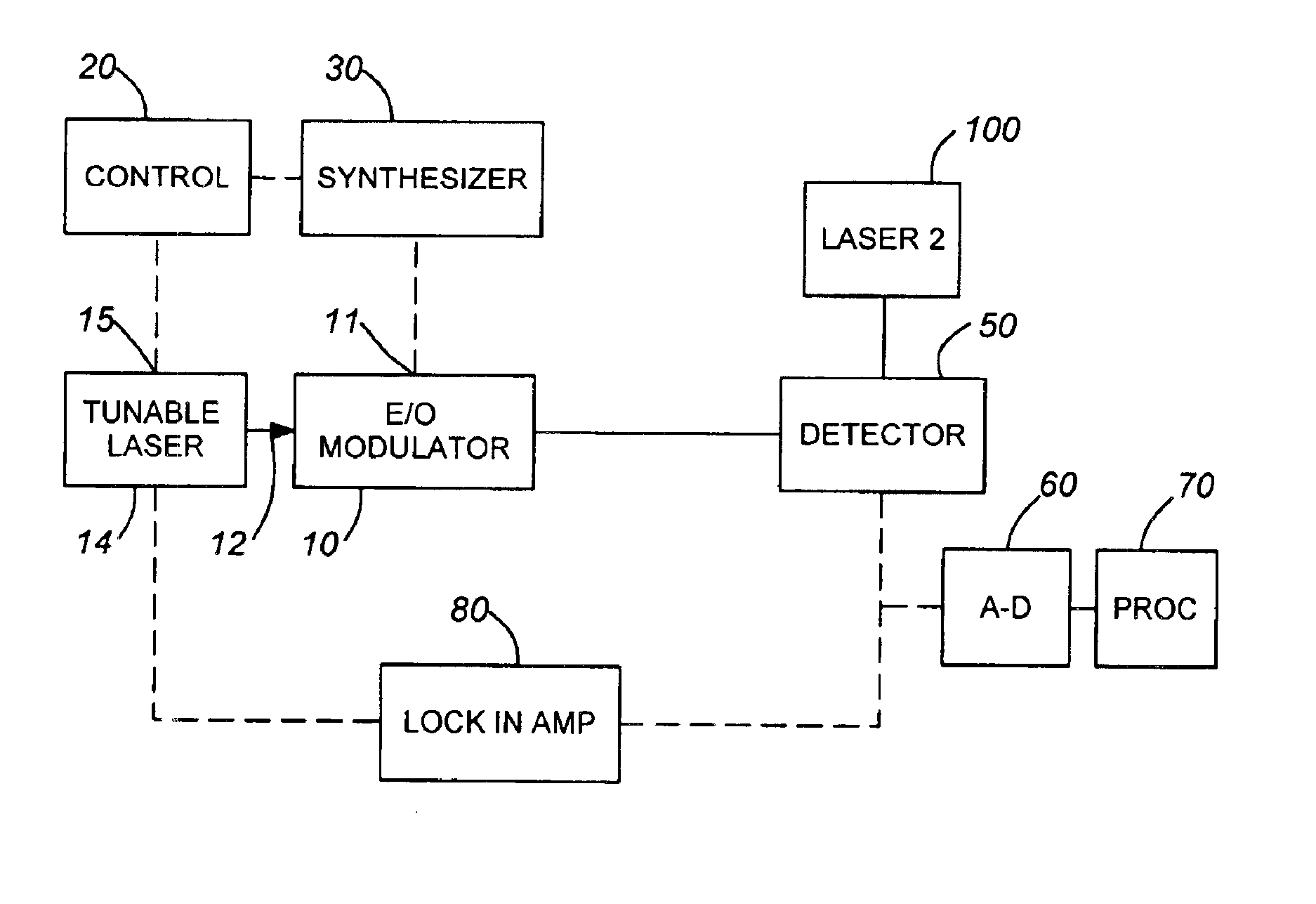
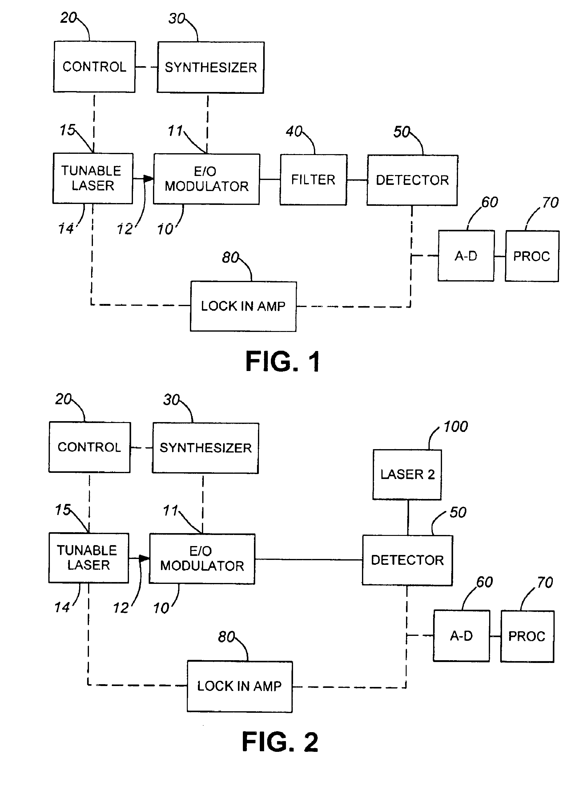
However, rather than being filtered by means of a relatively narrowband bandpass optical filter installed in the output path of the modulator 10, as in the first embodiment, the modulated beam output of modulator 10 in the embodiment of FIG. 2 is directly incident upon the optical aperture of the detector 50. In addition, a second laser 100 has its output beam coincidentally incident upon the same optical aperture of the optical detector 50. This may be effecting using a suitable coupler (not shown). This coincidence of the two laser beams on the beam receiving sensitivity region of the detector creates a heterodyne effect therebetween, resulting in sum and difference optical beat frequencies between the carrier frequency fc14 of the tunable laser 14 and the carrier frequency fc100 of the laser 100 at the optical detector's input aperture sensitivity region. The frequency fc100 of the laser 100 may be the same as or relatively close to the carrier frequency fc14 of the tunable laser...

second embodiment

Since the frequency difference between the sideband energy and the carrier fc14 produced by tunable laser 14 falls within the tuning window over which the modulation frequency is varied (e.g., 100 kHz to 50 GHz), then in order to use a relatively inexpensive optical detector having a relatively low frequency sensitivity range, it is necessary to remove this carrier from the optical detector input. As pointed out above, this is accomplished in the second embodiment by optically heterodyning the carrier frequency fc14 produced by tunable laser 14 with the output beam frequency fc100 of the second laser 100 at the optical sensitivity aperture of the detector 50.

As in the first embodiment, the resulting narrowband output of detector 50 may be digitized by A-D converter 60 for analysis by processor 70. Also, the phase response of the modulator may be measured by imparting a relatively low frequency signal to the tunable laser 14 as by means of lock-in amplifier 80, the output of which is...


PUM

PropertyMeasurementUnit
frequencyaaaaaaaaaa
frequencyaaaaaaaaaa
frequency sensitivityaaaaaaaaaa

Abstract

A mixed frequency-based method and arrangement for characterizing an electro-optic modulator is configured to vary the tuning of a laser beam, to be modulated by the optical modulator, simultaneously with and in the same manner as the variation in frequency of the modulation signal. The effect of this dual modulation approach is a modulated laser beam, in which the frequency difference between the carrier component of the laser beam and sideband energy produced by the modulation signal is controlled so that it falls within the sensitivity range of a relatively low cost optical detector.

Description

FIELD OF THE INVENTIONThe present invention relates in general to optical communication systems and component therefor, and is particularly directed to a new and improved method and arrangement for characterizing or testing the operation / performance of an electro-optic modulator of the type used to modulate a laser beam with a very high frequency information signal (e.g., a digital information signal having a data rate on the order of 40 Gbps or higher).BACKGROUND OF THE INVENTIONConventional techniques for characterizing electro-optic devices, particularly electro-optic modulators of the type used in digital optical communication systems, employ an opto-electronic detection subsystem having a bandwidth larger than highest modulation frequency to be measured. For characterizing a 40 Gb / s or high device, such a detection subsystem is expensive and difficult to calibrate.SUMMARY OF THE INVENTIONIn accordance with the present invention, these high cost and complex calibration shortcomi...

Claims


Application Information

Patent Timeline
Patent Type & Authority Patents(United States)
IPC IPC(8): G01M11/00G02F1/035G02F1/01
CPCG02F1/035G01M11/00
Inventor NYMAN, BRUCEMCBRIEN, GREGORY J.
Owner JDS UNIPHASE CORP
Why Eureka
Try Eureka