Cavity ringdown spectroscopy system and method

a ringdown spectroscopy and cavity technology, applied in absorption/flicker/reflection spectroscopy, spectrum investigation, instruments, etc., can solve the problems of inaccuracy of the exponential fit of ringdown data, the inability to switch the resonance off and on, and the intrinsic speed limitations of aom switching, etc., to achieve the effect of stabilizing the resonating optical field

Inactive Publication Date: 2005-03-08
BATTELLE MEMORIAL INST
View PDF23 Cites 57 Cited by
  • Summary
  • Abstract
  • Description
  • Claims
  • Application Information

AI Technical Summary

Benefits of technology

A further embodiment includes means for generating a resonating optical field including a light source coupled to an optical cavity; means for stabilizing the resonating optical field by providing feedback to the light source with servo circuitry coupled to the light source; and means for evaluating decay of the optical field in response to a control signal input to the servo circuitry. This control signal input can switch operation between two or more different resonant modes of the optical cavity by corresponding switching between different frequencies of a CW laser form of the light source.
Another embodiment of the present invention includes performing cavity ringdown spectroscopy with an optical resonator and a laser device. The laser device is stabilized with circuitry that receives a feedback signal corresponding to detected output light of the laser device. The circuitry further receives a control signal that can correspondingly cause a change in one or more output characteristics of the laser device, such that a selected resonant mode of the resonator can be readily discontinued to evaluate ringdown. In one form, switching between different resonant modes of the resonator is performed. The characteristics determined with this system can include evaluation of reflectivity of one or more mirrors included in the resonator and / or evaluation of a sample placed in the resonator. The circuitry can be in the form of a servo device with a feed forward input receiving the control signal and a feedback input receiving the detected heterodyne signal between the cavity mode and the incident field from the laser. The laser device can be in the form of a current-controlled continuous wave type, such as a quantum cascade laser or laser diode variety. The optical resonator can include two or more mirrors in an optical cavity. The optical cavity can be arranged to selectively receive an analyte for evaluation.
Another embodiment includes operating an optical cavity responsive to light and providing a feedback signal from a servo device to stabilize operation of the light source at a selected frequency. A control signal is also provided to the servo device to adjust operating frequency of the light source. The embodiment further includes switching between different resonant modes of the cavity in response to the control signal and evaluating decay for each of the different resonant modes.
Still another embodiment of the present invention includes providing light from a laser device to an optical resonator to operate the resonator in a first resonant mode; receiving a feedback signal representative of the light output with servo circuitry coupled to the laser device to stabilize operation of the resonator in the first resonant mode; and halting the operation of the cavity in the first resonant mode in response to a control signal provided to the circuitry to evaluate decay of an optical field corresponding to the first resonant mode. The laser device can be of a current-controlled continuous wave type such as a quantum cascade laser or laser diode variety and / or the servo circuitry can include a feed forward arrangement for receiving the control signal. The optical resonator can include two or more mirrors in an optical cavity arranged to selectively receive an analyte for evaluation.

Problems solved by technology

On the other hand, with CW laser CRDS, the need to switch the resonance off and on can be more complicated.
Because an AOM provides a traveling wave with an acoustic grating that takes some time to form and dissipate, AOM switching typically has intrinsic speed limitations.
These limitations can result in inaccuracies of the exponential fit of ringdown data, especially in the mid-wavelength to long-wavelength infrared ranges for which the AOM device is typically bigger and slower.
These frequency lock techniques typically increase the complexity of the switching schemes used with CW laser CRDS.

Method used


Image

  • Cavity ringdown spectroscopy system and method
  • Cavity ringdown spectroscopy system and method
  • Cavity ringdown spectroscopy system and method

Examples


experimental example

The present invention will be further described with reference to the following specific example. It will nevertheless be understood that this example is merely illustrative and is not intended to restrict or otherwise limit the scope of the present invention.

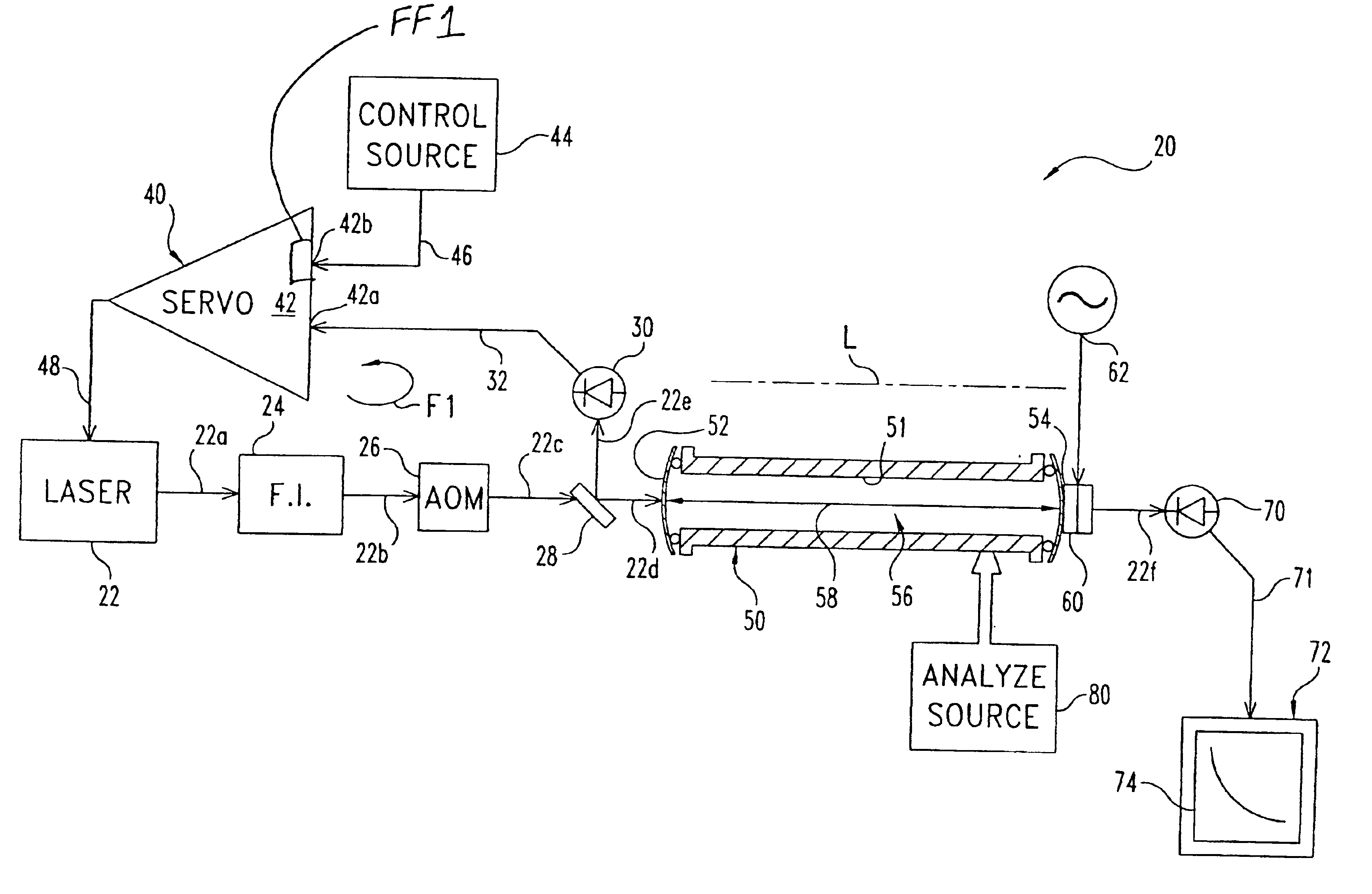
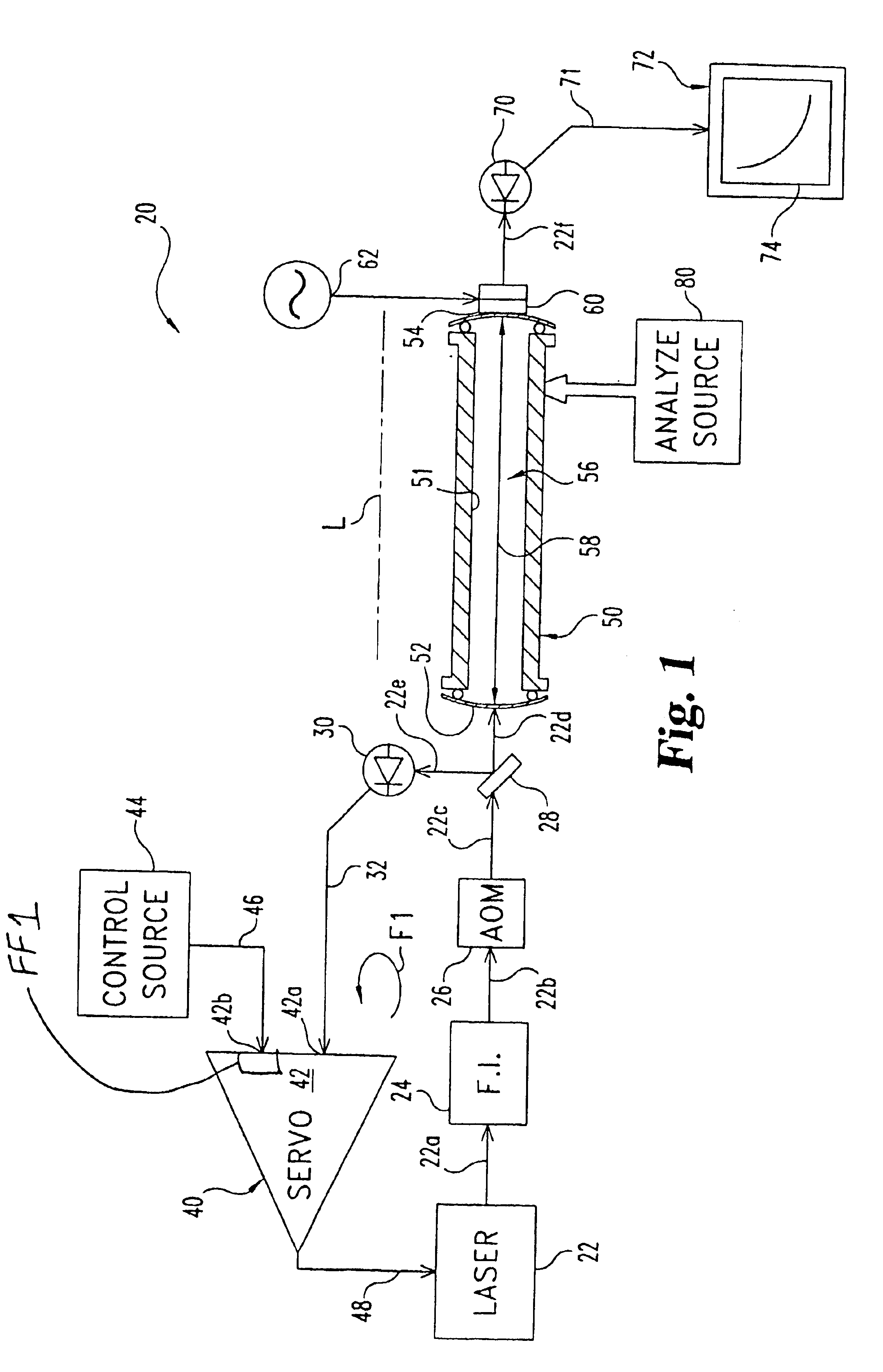
FIG. 3 shows ringdown data taken with an experimental arrangement of the type shown in FIG. 1. This arrangement shows an inverted exponential decay averaged over 100 sweeps, and a weighted exponential fit. It should be understood that the relatively quick and reproducible switching available with this technique allows meaningful averages to be taken without drift, washout, or various noise effects. The parameters of the exponential fit determine the ringdown time, facilitating a quick and accurate determination of the reflectivities of the mirrors used in the optical cavity. Similar experiments can be conducted to evaluate analytes as previously described in connection with FIGS. 1 and 2.


PUM

PropertyMeasurementUnit
optical fieldaaaaaaaaaa
current flowaaaaaaaaaa
frequencyaaaaaaaaaa

Abstract

One embodiment of the present invention includes an optical cavity, a source to provide light to the optical cavity, a sensor to detect the light and generate a corresponding sensor signal, and a servo device including a feedforward input and a feedback input. Feedback from the sensor signal is provided to the servo device to regulate operation of the source at a frequency selected to generate an optical field resonating in the first mode in the cavity. An input device provides a control signal to a control input of the servo device that selectively alters operation of the light source to corresponding halt resonance in the first mode. An evaluation device is also included to evaluate decay of the optical field after resonance in the first mode is halted.

Description

BACKGROUNDThe present invention relates to cavity ringdown spectroscopy, and more particularly, but not exclusively relates to servo-switched frequency control of a light source for an optical resonator.Cavity Ringdown Spectroscopy (CRDS) is a technique that, among other things, is directed to making absorption measurements with sensitivities that can be better than many other systems. In a typical CRDS system, the optical resonator includes two or more mirrors in an optical cavity aligned so that incident light circulates between them. The sample of absorbing material is placed in the cavity for interrogation. When input light to the resonator is discontinued, the radiant energy stored in the resonator decreases over time or “rings-down.” For an empty cavity, the stored energy follows an exponential decay characterized by a ringdown rate that depends on the reflectivity of the mirrors, the separation between the mirrors, and the speed of light in the resonator. If an absorbing samp...

Claims


Application Information

Patent Timeline
Patent Type & Authority Patents(United States)
IPC IPC(8): G01N21/31G01N21/39
CPCG01N21/39G01N21/031G01J3/42G01N2021/391
Inventor TAUBMAN, MATTHEW S.
Owner BATTELLE MEMORIAL INST
Why Eureka
Try Eureka