Method and apparatus for automatic capture verification using polarity discrimination of evoked response

a technology of polarity discrimination and automatic capture, applied in the field of implantable cardiac stimulation devices, can solve the problems of reducing detection accuracy, reducing detection accuracy, and reducing detection accuracy, so as to improve detection accuracy, minimize interference, and improve discrimination

Inactive Publication Date: 2005-03-08
PACESETTER INC
View PDF3 Cites 26 Cited by
  • Summary
  • Abstract
  • Description
  • Claims
  • Application Information

AI Technical Summary

Benefits of technology

The present invention addresses this need by providing an implantable cardiac stimulation device that has the capability to adjust the processing of the post-pacing sensed signals, such that the capture-detection feature is “phasically placed” to enhance capture verification. More specifically, the stimulation device is capable of performing reliable capture verification using sensing circuitry that allows the evoked response and polarization signals to be distinguished by their polarity.
The methods and features included in the present invention improve capture detection by sensing an evoked response using methods that minimize interference by the polarization signal artifact allowing improved discrimination between evoked response and polarization signals.

Problems solved by technology

While this approach is straightforward, it quickly depletes battery energy and can result in patient discomfort due to extraneous stimulation of surrounding skeletal muscle tissue.
Sensing an evoked response locally, however, can be difficult because of lead polarization that occurs at the lead-tissue interface whenever a stimulation pulse is delivered.
This undesirable situation occurs often because the polarization signal can be three or more orders of magnitude greater than the evoked response signal.
Furthermore, the lead polarization signal is not easily characterized; it is a complex function of the lead materials, lead geometry, tissue impedance, stimulation energy and other variables, many of which are continually changing over time.
In each of the above cases, the result may be a false positive detection of an evoked response.
Such an error leads to a false capture indication, which in turn leads to missed heartbeats, a highly undesirable and potentially life-threatening situation.
Another problem results from a failure by the pacemaker to detect an evoked response that has actually occurred.
In that case, a loss of capture is indicated when capture is in fact present, which is also an undesirable situation that will cause the pacemaker to unnecessarily invoke the threshold testing function in a chamber of the heart.
However as, processing algorithms become more complicated, additional microprocessing time is required, which is already limited due to the numerous device functions that must be performed, and battery consumption is increased.
The use of additional physiological sensors, however, adds cost, more complicated software and hardware requirements, and increases reliability issues and implant time.

Method used


Image

  • Method and apparatus for automatic capture verification using polarity discrimination of evoked response
  • Method and apparatus for automatic capture verification using polarity discrimination of evoked response
  • Method and apparatus for automatic capture verification using polarity discrimination of evoked response

Examples


Embodiment Construction

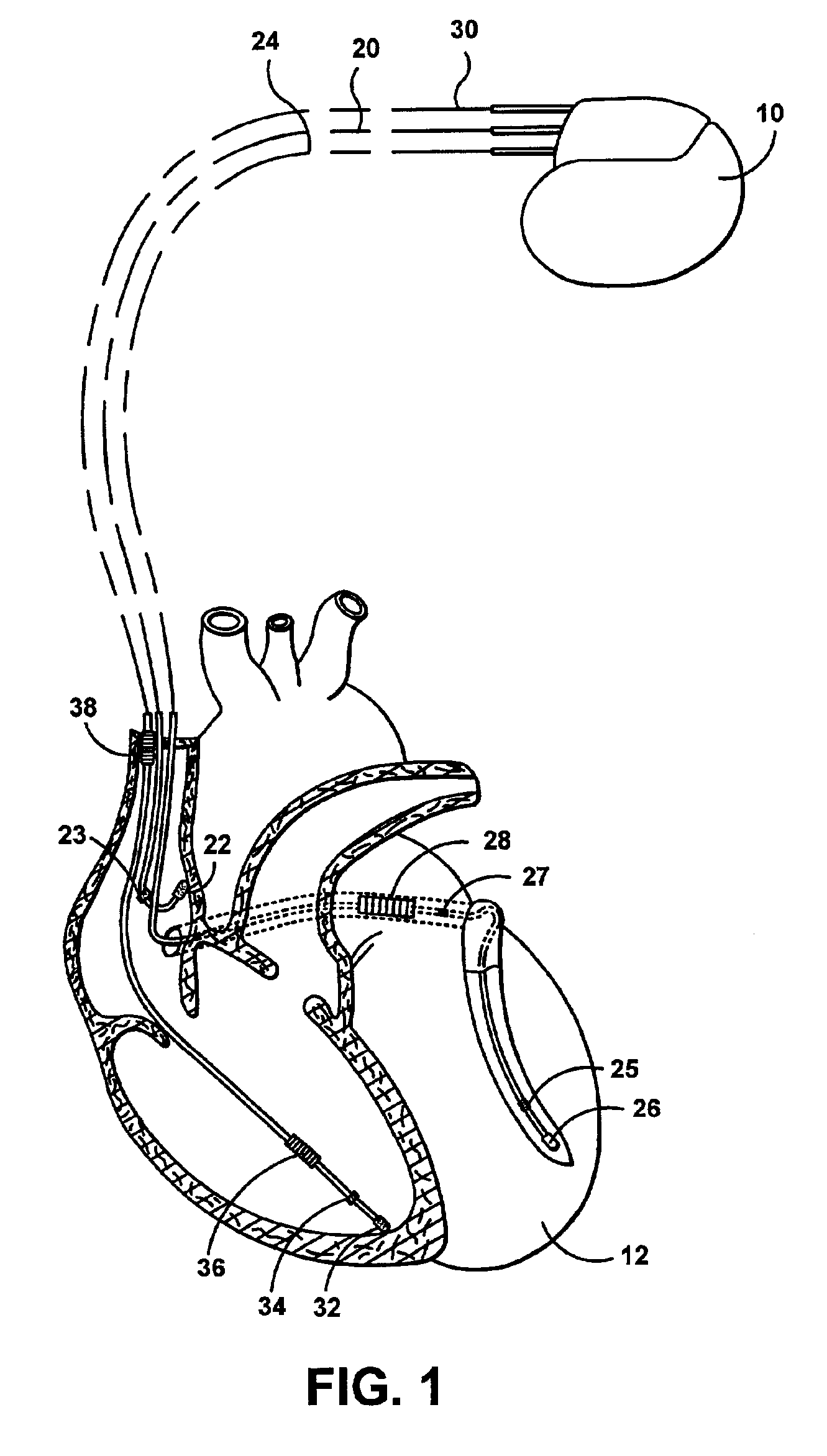
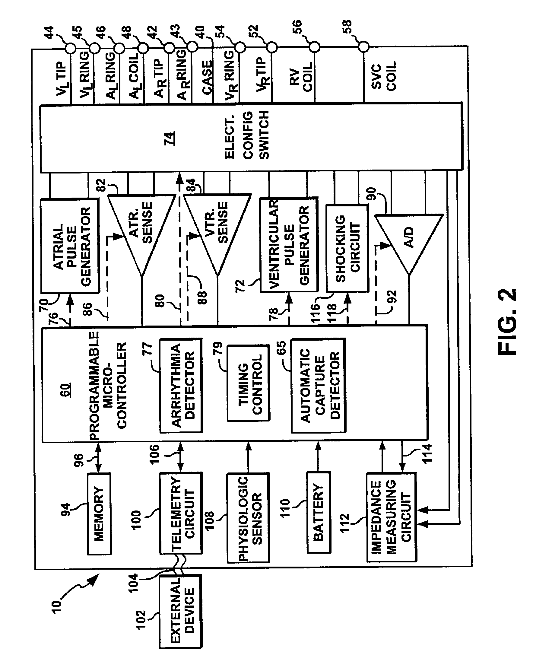
The following description is of a best mode presently contemplated for practicing the invention. This description is not to be taken in a limiting sense but is made merely for the purpose of describing the general principles of the invention. In the description of the invention that follows, like numerals or reference designators will be used to refer to like parts or elements throughout. The present invention is directed at providing automatic capture verification in an implantable cardiac stimulating device possessing pacemaking, cardioversion and defibrillation capabilities. A general cardiac stimulation device will thus be described in conjunction with FIGS. 1 and 2, in which the capture detection circuitry and methods included in the present invention could be implemented. It is recognized, however, that numerous variations of such a device exist in which the methods of the present invention could be implemented without deviating from the scope of the present invention.

FIG. 1 i...


PUM


Abstract

A cardiac stimulation device and method automatically confirm capture by detecting the polarity of a post-stimulation signal. A capture detection circuit is subjected to recharge and block overlap signals applied such than an evoked response signal is characterized by a primarily positive polarity and a polarization signal is characterized by a primarily negative polarity. An amplitude detection feature, such as peak amplitude or signal integral, and its polarity are determined from a post-stimulation signal sensed by the capture detection circuit during a capture detection window. Capture is confirmed when the amplitude detection feature has a positive polarity.

Description

FIELD OF THE INVENTIONThe present invention relates to an implantable cardiac stimulation device capable of automatically verifying capture. More specifically, the present invention relates to a device and method wherein sensing circuitry allows capture detection based on the determination of the polarity of a post-stimulation signal feature.BACKGROUND OF THE INVENTIONIn the normal human heart, the sinus node, generally located near the junction of the superior vena cava and the right atrium, constitutes the primary natural pacemaker initiating rhythmic electrical excitation of the heart chambers. The cardiac impulse arising from the sinus node is transmitted to the two atrial chambers, causing a depolarization known as a P-wave and the resulting atrial chamber contractions. The excitation pulse is further transmitted to and through the ventricles via the atrioventricular (A-V) node and a ventricular conduction system causing a depolarization known as an R-wave and the resulting ven...

Claims


Application Information

Patent Timeline
Patent Type & Authority Patents(United States)
IPC IPC(8): A61N1/362A61N1/37
CPCA61N1/3712A61N1/3716
Inventor BRADLEY, KERRY
Owner PACESETTER INC
Why Eureka
Try Eureka