
Method and apparatus for noise tomography

a technology of noise tomography and methods, applied in the field of methods and apparatus for noise tomography, can solve problems such as the difference between traditional methods and encoding functions

Inactive Publication Date: 2005-03-08
INVIVO CORP
View PDF5 Cites 57 Cited by
  • Summary
  • Abstract
  • Description
  • Claims
  • Application Information

AI Technical Summary

Benefits of technology

"The invention is about a way to use RF probes to measure the heat produced by a sample, like a body, and create a 3D map of its conductivity. This method is non-invasive and doesn't require any external power, chemicals, or radionuclides to be introduced into the body. It can be used alone or in combination with other imaging techniques."

Problems solved by technology

However, the new methods of partially paralleled imaging, for example SENSE and SMASH, demonstrate that the probe sensitivity patterns can be considered encoding functions, and these encoding functions are different from traditional methods.
This is true because the electronic thermal noise of the tissue is normally dominant and the physical size and structure of the coil dictate the acquisition site of the “body” noise.

Method used


Image

  • Method and apparatus for noise tomography
  • Method and apparatus for noise tomography
  • Method and apparatus for noise tomography

Examples


example 1

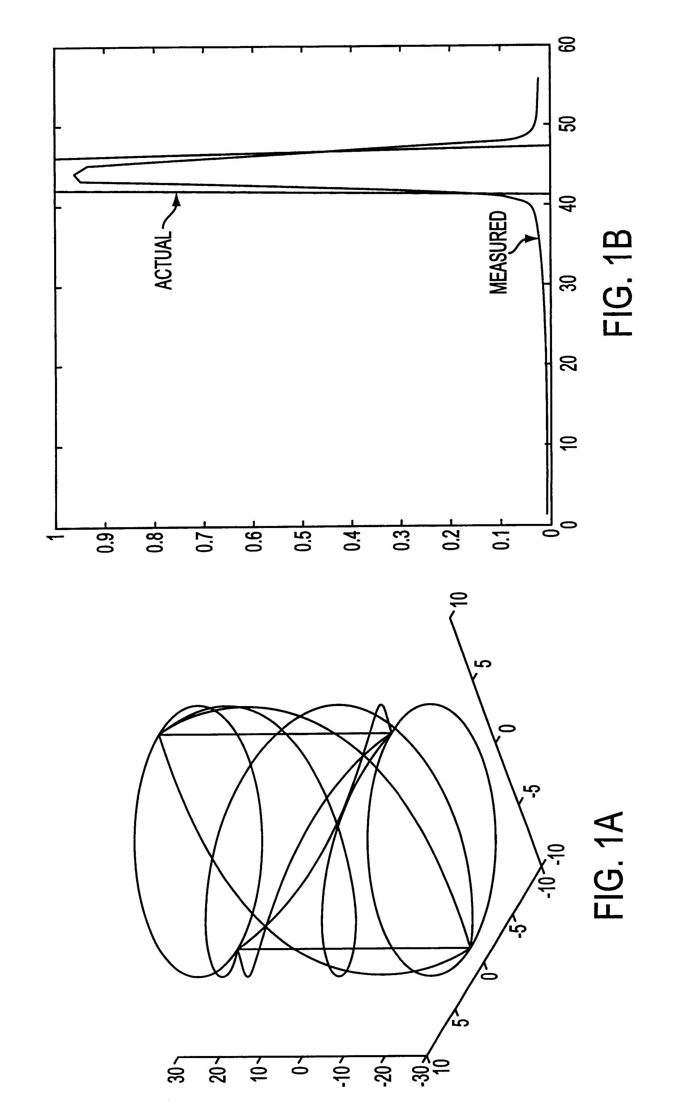
A one-dimensional experiment was preformed using a four-coil FACT array, with a length of 55 cm long and diameter of 18 cm. The electromagnetic fields in the sample region for each of the four elements and the z dependence of the six independent values in the covariance matrix with respect to the insertion of a cylindrically symmetric phantom into the coils. The z dependence of normalized noise covariance matrix in this calculation is assumed to be proportional to ∫{right arrow over (E)}k·σ·{right arrow over (E)}m*rdrdθ. This assumption comes from the reciprocity theorem which relates the voltage detected on each channel, for an arbitrary current, J, at some location within the sample, will be proportional to J·Ek, where Ek, is the electric field generated by a unitary amplitude oscillating current on the kth probe. Using the assumption that the local current distribution within the sample can be described by a Thevenin's current source equivalent circuit for the Nyquist / Johnson mod...

example 2

One-Dimensional Embodiment of the Subject MR-NT Technique

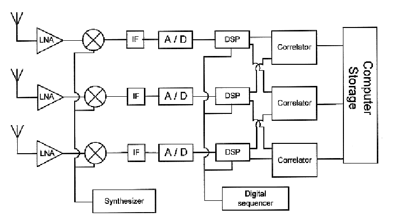
In a one dimensional embodiment of the subject MR-NT method and apparatus, a coil array was utilized. The coil array uses Fourier Array Coil Technology (FACT) [DGR], pioneered by MRI Devices Corporation. of the coil array can also incorporate one or more versions of a spiral birdcage introduced by Alsop, et al [ACM]. A spiral birdcage coil can produce a magnetic field that is nearly sinusoidal in the X and Y directions. Because the sines and cosines form an orthogonal basis, and if the endring currents are ignored, noise sensitivity functions for multiple FACT coils with different spatial frequencies should form a nearly orthogonal set for a uniform sample.

A FACT coil array consisting of four coils including a −π rotation, a 0 rotation, a +π rotation and a 2π rotation, as shown in FIG. 3-1, was used in the one-dimensional experiment of the MR-NT technique.

With supplemental isolation methods, adequate isolation from inductive c...

example 3

Two Dimensional Experiment of the Subject MR-NT Method and Apparatus

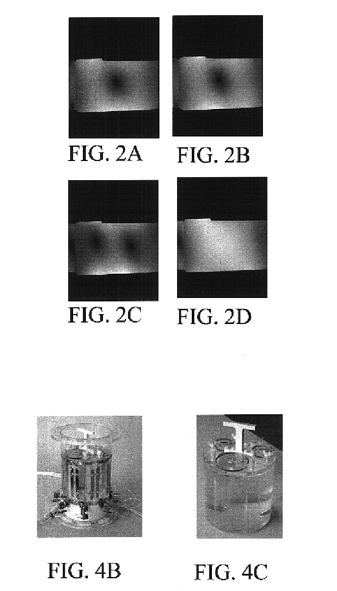
A specific phantom and coil array were produced to be used in conjunction with a 1.5 T 8 channel MRI system. A two-dimensional test of the subject MR-NT method was preformed using an RF array, as shown in FIG. 4B, that was based on an eight-channel MRI head coil by MRI Devices Corporation. The array incorporates eight resonance tuned loop probes, each loop sweeping an angle of 57 degrees, with a height of 180 mm. The coil array was constructed on a 215.9 mm(8.5″) OD Acrylic tube. Each of the coils was overlapped with its nearest neighbors, providing approximately 20 dB of isolation from its nearest neighbors. This coil is a poor design for MR-NT for the same reason that it is a good design for an MRI coil: because of the symmetrical design, the electric field at the center of the coil is zero. The coil does have significant electric fields in the perimeter, and the phantom was designed with this in mind.

In order to ...


PUM


Abstract

The subject invention pertains to an imaging technique and apparatus which can utilize an array of RF probes to measure the non-resonant thermal noise which is produced within a sample, such as a body, and produce a non-resonant thermal noise correlation. The detected noise correlation is a function of the spatial overlap of the electromagnetic fields of the probes and the spatial distribution of the conductivity of the sample. The subject technique, which can be referred to as Noise Tomography (NT), can generate a three-dimensional map of the conductivity of the sample. Since the subject invention utilizes detection of the thermal noise generated within the body, the subject method can be non-invasive and can be implemented without requiring external power, chemicals, or radionuclides to be introduced into the body. The subject imaging method can be used as a stand along technique or can be used in conjunction with other imaging techniques.

Description

BACKGROUND OF INVENTIONHistorically, the electronic noise, generated within the sample, has not been encoded during the Magnetic Resonance imaging (MRI) process and the pulse sequences and gradient encoding have not encoded the noise. However, the new methods of partially paralleled imaging, for example SENSE and SMASH, demonstrate that the probe sensitivity patterns can be considered encoding functions, and these encoding functions are different from traditional methods. The sensitivity patterns can encode the noise to approximately the same extent that they encode the signal. This is true because the electronic thermal noise of the tissue is normally dominant and the physical size and structure of the coil dictate the acquisition site of the “body” noise. Although the regions of MRI signal acquisition and noise acquisition are similar they are not the same, because the probe's magnetic field is associated with signal acquisition, for example MRI signal acquisition, whereas the pro...

Claims


Application Information

Patent Timeline
Patent Type & Authority Patents(United States)
IPC IPC(8): A61B5/055A61B5/053G01R33/44
CPCA61B5/0507A61B5/0536G01R33/44A61B5/055A61B2562/02A61B2562/046
Inventor DUENSING, G. RANDYSAYLOR, CHARLESHUANG, FENG
Owner INVIVO CORP
Learn More