Method for synchronizing a local time base on a central time base and device for implementing said method with preferred applications

a technology of a local time base and a central time base, which is applied in the direction of generating/distributing signals, programme control, electric programme control, etc., to achieve the effect of increasing the “softness” of the application and being highly accura

Inactive Publication Date: 2005-03-08
HANGER SOLUTIONS LLC
View PDF10 Cites 14 Cited by
  • Summary
  • Abstract
  • Description
  • Claims
  • Application Information

AI Technical Summary

Benefits of technology

According to a further advantageous embodiment of the method according to the invention, a correction value corresponds to the initial value of a control algorithm, to which the value zero is supplied as the set value, and to which the minimum value of the time discrepancies in an observation period is supplied as the actual value. On the one hand, this embodiment effectively further increases the “softness” of the application of correction values to a local timebase, i.e and in particular application to the timer modules of an associated local data processing unit.
Finally, the use of a control algorithm for determining a correction value makes it possible for the method according to the invention to be implemented virtually completely with the aid of software routines which run in the local data processing unit having the respective local timebase. The respective correction value may thus be determined purely by software then just needs to be loaded as a new start value in the timer module of the local data processing unit. Such a start value may also be referred to a reload value. This is associated with the furthe

Problems solved by technology

Such jitter may have widely differing causes and, for example, may be due to transmission interference between the central timebase and the local timebases,

Method used


Image

  • Method for synchronizing a local time base on a central time base and device for implementing said method with preferred applications
  • Method for synchronizing a local time base on a central time base and device for implementing said method with preferred applications
  • Method for synchronizing a local time base on a central time base and device for implementing said method with preferred applications

Examples


Embodiment Construction

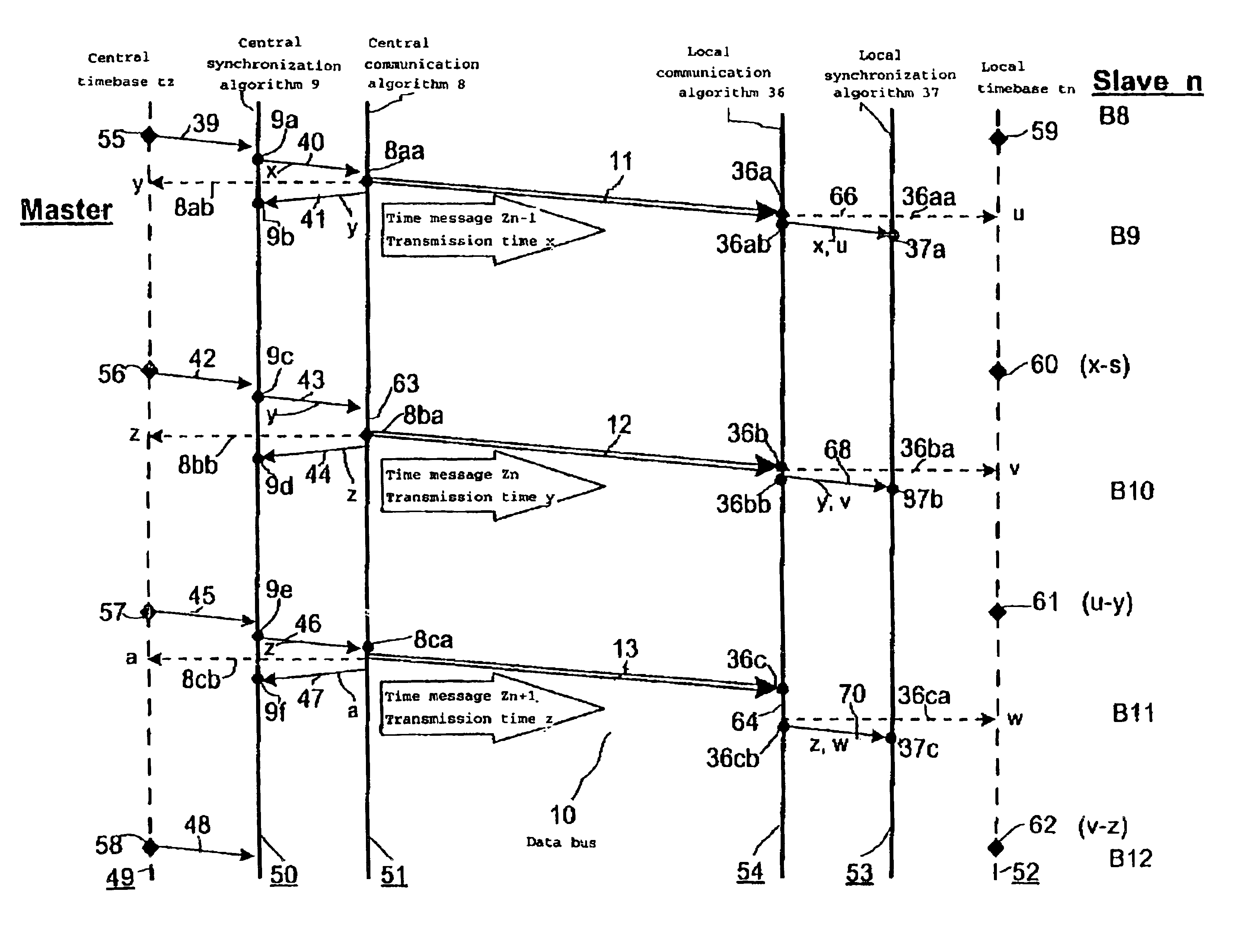
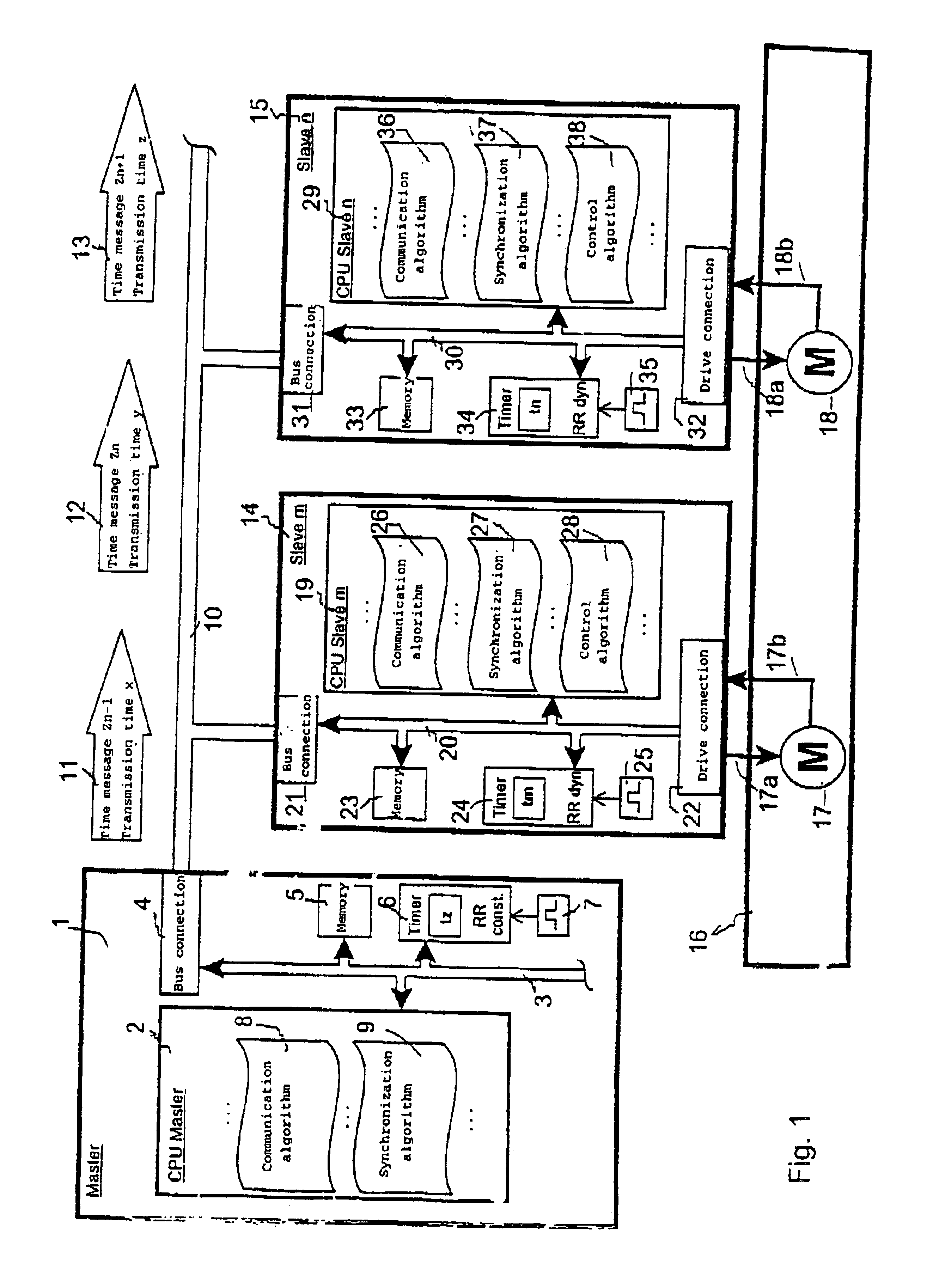
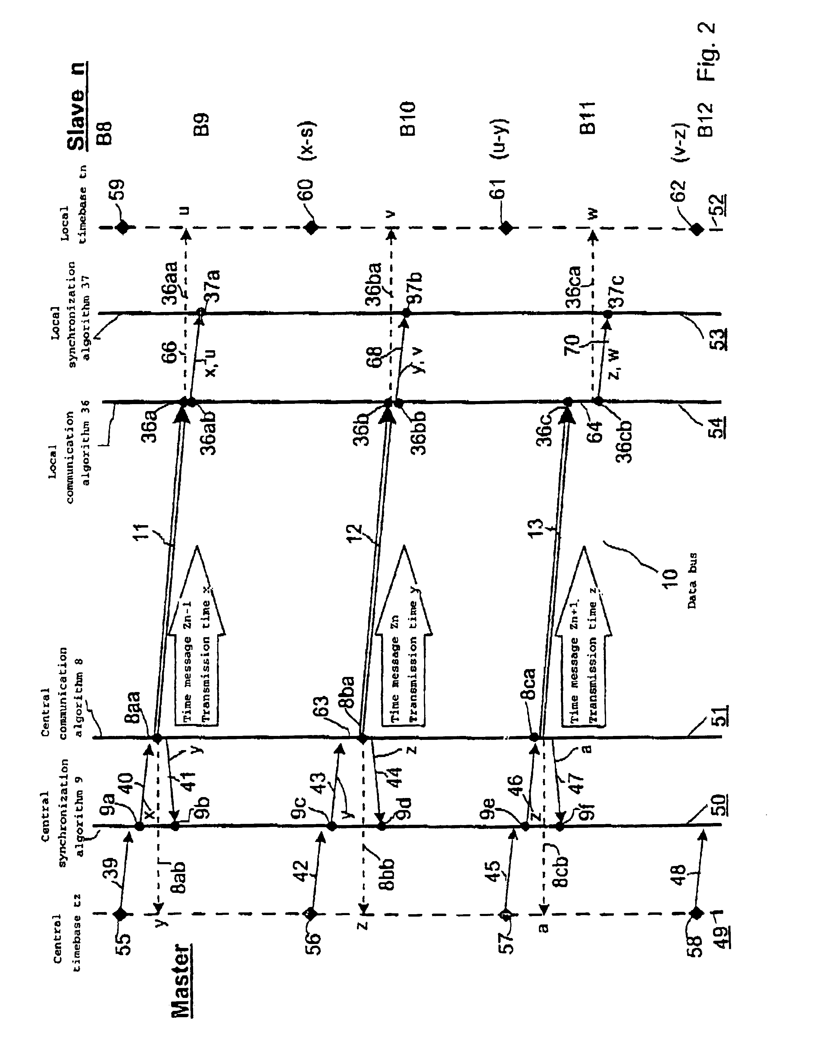
FIG. 1 shows an advantageous arrangement, in the form of an example of a block diagram, which is suitable for carrying out the method according to the invention. The arrangement contains a central data processing device 1, which is also referred to as a “master” and, by way of example, two local data processing devices 14 and 15, which are also referred to as the “slave m” and “slave n”. All the data processing devices are connected one another via an external data bus 10, wherein data messages are transmitted with time information, that is to say time messages, from the central data processing device 1 to the local data processing devices 14 and 15. In the example in FIG. 1, three successive time messages 11, 12 and 13 are shown by way of example from a stream of messages which follow one another at regular intervals and are also referred to as time messages Zn−1, Zn and Zn+1. As data information, each time message 11, 12, 13 contains the value of the transmission time x, y, z of a...


PUM


Abstract

Time messages are transmitted from a central timebase to a local timebase. The transmission time of a time message is detected and is entered as a data value in a subsequent time message. The reception time of a time message is detected, and the transmission time contained in it is reproduced, by the local timebase. Finally, the difference between associated transmission and reception times of time messages is used to determine the time discrepancies occurring in the process, and these are evaluated for synchronization of the local timebase.

Description

FIELD OF THE INVENTIONThe invention relates to a method for synchronization of at least one local timebase in a local technical system to a central timebase in a central technical system. The invention also relates to an apparatus for carrying out the method, and to preferred uses of the apparatus.In this case, the local timebase may correspond to the timing in a local data processing device, and the central timebase may correspond to the timing in a central data processing device. Data records are transmitted from the central data processing device to the local data processing device and thus from the central timebase to the local timebase, time base data records contain time information and, in some circumstances, also other payload data of widely differing types. These data records are referred to, for short, as “time messages” in the following text.BACKGROUND OF THE INVENTIONAs a rule, the local processing of data in the local data processing device is carried out on the basis o...

Claims


Application Information

Patent Timeline
IPC IPC(8): G05B19/418G05B19/04G05B19/042G06F1/14G06F13/00H04L7/00
CPCG05B19/0421G06F1/14G05B19/41865Y02P90/02
Inventor KRAUSE, KARL-HEINZZEBISCH, THOMAS
Owner HANGER SOLUTIONS LLC
Why Eureka
Try Eureka